
Mic pre amp

The microphone preamplifier circuit based on the TLC251 is designed to amplify low-level audio signals from microphones while maintaining low power consumption, making it suitable for battery-operated devices. The TLC251 is notable for its low quiescent current, which is particularly beneficial in portable applications.
The BIAS pin plays a crucial role in configuring the operational mode of the amplifier. By applying a positive voltage to this pin, the circuit enters a low-power state, which is essential for extending battery life in mobile applications. In this state, the operational amplifier operates efficiently, ensuring that audio signals are amplified without significant power drain.
The schematic typically includes additional components such as resistors and capacitors that set the gain of the amplifier and filter out unwanted noise. Input capacitors may be used to block DC offsets from the microphone signal, while feedback resistors determine the gain of the amplifier. The output stage may also include coupling capacitors to ensure that the amplified signal is appropriately interfaced with subsequent stages in the audio processing chain.
Overall, the design of the microphone preamplifier using the TLC251 is optimized for low power consumption while providing high-quality audio amplification, making it a reliable choice for various audio applications.Mic pre amp schematic based TLC251. TLC251 is a Programmable Low-Power Operational Amplifiers. This is indeed a control input, called BIAS (pin 8), which determines the mode of operation. When the pin is worn on the positive potential of power supply, the consumption of the circuit is reduced to a minimum, which is 10 uA (ten micro-amps). 🔗 External reference
Related Circuits
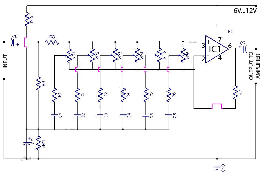
This circuit is a six-band graphic equalizer that allows modification of sound across low, mid, and high frequencies using an IC 741 operational amplifier. It enables management and mixing of frequencies and tones as desired. The audible frequency spectrum...
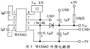
The widespread application of Flash technology in microprocessors has led to significant advancements in the development and utilization of one-chip computers. Designers have transitioned from traditional in-circuit emulators (ICE) and JTAG interfaces to more cost-effective and user-friendly development methods....
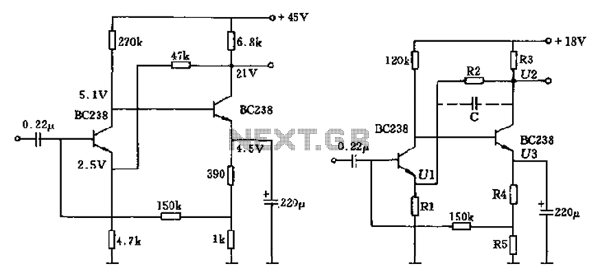
The circuit characteristic involves the elimination of external input resistors, which reduces the influence on the stabilization of the working point. It also employs two DC negative feedback loops. Additionally, the output from the second stage connects to the...
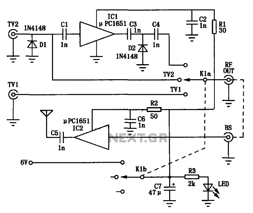
Amplification is utilized to convert video output signals from various devices, such as VCRs and DVD players, which often require amplification of weak output signals. Additionally, it can transmit radio frequency signals over a radius of approximately 7 meters,...

This is a high-fidelity, high-quality audio amplifier circuit diagram. A pre-amplifier is not required. Component list: R1, R4 = 47K 1/4W resistors; R2 = 4.7K 1/4W resistor; R3 = 1.5K 1/4W resistor; R5 = 390Ω 1/4W resistor; R6 =...
A condenser microphone (electret type with two terminals) is to be powered. A resistor of 1 kΩ and a capacitor of 10 µF have been connected to its positive terminal, while the other terminal is grounded. To power an electret...