
Telecard reader with AT90s2313 micro

The circuit design employs the AT90S2313 AVR microcontroller, which is a popular choice for embedded applications due to its compact size and efficient performance. The microcontroller interfaces directly with the telecard's EEPROM memory, allowing it to extract the relevant data stored within. The memory architecture of the telecard is structured such that the first 8 bytes are reserved for essential information, which includes the country code, credit units, and customer identification. The remaining bytes are allocated for the unique serial number of the card, which can be critical for tracking and authentication purposes.
The MAX232 chip serves as a vital component in ensuring proper communication between the microcontroller and the PC. It converts the RS232 signal levels to TTL levels suitable for the microcontroller, enabling reliable data transmission. The choice of using HyperTerminal software allows users to interact with the circuit easily, providing a user-friendly interface to view and analyze the data read from the telecard.
For enhanced functionality, integration of an LCD display could be considered in future iterations of the circuit, allowing for immediate visual feedback of the data without the need for a PC connection. Additionally, implementing an automatic card detection feature via the telecard holder switch streamlines the user experience, facilitating hands-free operation.
Overall, this circuit serves as an educational tool for understanding the principles of microcontroller-based reading systems and can be a foundational project for those looking to explore more complex electronic systems and applications.This circuit is onlyreader. It`s not programmer. You CANNOT refill, hack or any illegal thing, the telecards. The purposeof this circuit is for you to understand how a microcontroller readsthetelecard, forbuilding other electronic circuits such as"electronic safety lock" or"Checker for how much units (credits) leftin the card" etc. This reader can read the contained memory of the telecard. These cards have 64 bytes ( 512 bits) of eeprom memory that the first 8 bytes ( 64 bits ) arewrite protected. They areonly for reading. This circuit does not include any lcd display, to keep the cost low, but the data can be viewed to any PC system using the RS232 port, by the Hyper terminal software.
The circuit based on AT90S2313 AVR microcontroller from atmel, programmed with telecard. hex and telecard. eep. The converter from + - 12V of RS232 to TTL and from TTL to + - 12V is MAX232. When you build the circuit ( i think its very simple ), connect the reader with RS232 port of the PC, run the Hyper terminal software ( start programs - accessories communications Hyper terminal ) and set the baud rate to 19200 bps 8 none 1. If you use a telecard holder, usually this holderincludes a switch that is pressed when you insert the card.
You can use this switch, to make the reading of the card, automatic. The 1st (85) and 2th (FC) byte it`s the country. The 3th (0B) is the units (3000) and 4th is the customer (OTE). These results are fromtesting of 50 different Greek telecards and i don`t know if they are correct. The 5th, 6th, 7th and 8th bytes are the serial number of the card in hex form. If you convert the 4A037AA0 hex ( bytes 8 to 5 ) to decimal, you will get the number 1241741984 ( look at the serial number of the black telecard above ). 🔗 External reference
Related Circuits
If an application utilizes a MOSFET to switch a load, it is straightforward to incorporate short-circuit or overload protection. This can be achieved by leveraging the internal resistance RDS(ON), which generates a voltage drop proportional to the current flowing...
The power supply section is the important one. It should deliver constant output regulated power supply for successful working of the project. A 0-12V/500 mA transformer is used for this purpose. The primary of this transformer is connected in...
The circuit consists of three stages, an electret microphone, an audio amplifier and an RF oscillator. The electret microphone consists of only two parts - a FET transistor and a plastic diaphragm. There is nothing else inside the case....
Condenser microphones generally provide superior sound quality compared to dynamic microphones. For those unfamiliar with these two microphone types, a Wikipedia article can offer useful insights. Electret condenser microphones consist of two plates (capacitors), one of which vibrates in...
The circuit is shown in Figure 1, and as described above, uses a voltage doubler rectifier. Diodes D1 and D2 are 1N4004 or similar. From there, a pair of resistors provide additional smoothing to the secondary filter caps. R3...
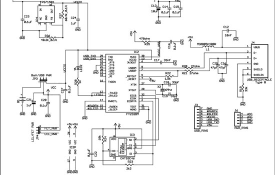
As found in SLAA458, the revised pulse oximeter application, an image of the USB schematic is attached, which is used to output collected data. There are a few questions regarding this schematic: 1) What do J3 and J6 correspond...