
tube power amplifier with el34 35w

The described amplifier is a push-pull design that leverages the characteristics of the EL34 vacuum tubes to achieve a power output of 35 watts. The push-pull configuration allows for improved efficiency and reduced distortion compared to single-ended designs, making it a preferred choice for audio applications. The amplifier's circuit typically includes a phase splitter to drive the two EL34 tubes, ensuring that one tube amplifies the positive half of the audio signal while the other amplifies the negative half.
The power supply section of the amplifier is critical, especially considering the original design utilized a tube rectifier. Replacing it with diodes simplifies the power supply design and enhances reliability, as diodes have a longer lifespan and better thermal stability. The output transformer is a pivotal component, as it matches the high impedance of the tubes to the lower impedance of the speakers. The transformer must be selected carefully; it should be rated to handle the power output and have the appropriate turns ratio to ensure optimal performance.
Safety precautions are paramount when working with high-voltage tube amplifiers. Proper insulation, secure connections, and adherence to safety protocols are essential to prevent electric shock. Individuals attempting to construct this amplifier should have a solid understanding of electronics, particularly in high-voltage applications, and should be familiar with soldering techniques and circuit assembly.
In summary, this amplifier design represents a historical yet functional piece of audio technology, requiring both skill and careful consideration in its construction and maintenance.It`s a classic designing of final amplifier 35 W, with two EL34 in push-pull, from the Siemens and Halske, with year of designing 24/3/1953 and code SV410/1. The amplifier it worked from 1954 until 1989, whenever it came also out except operation, with mean of operation 15 hours per day.
It did not present particular damage beyond the replacement of tubes, resistances and capacitors, result of natural deterioration. A essential change became with the replacement of restoring provision from tube, with diodes. The alone problem that will exist, for those who they try his manufacture, will be the transformer of expense, (it is in effect for all the tube manufactures), one and code that exists it will help. It can be replaced with a classic transformer of expense suitable for EL34. In his manufacture it needs (it is in effect for all the corresponding circuits), enough experience and attention in high voltage, danger of ELECTRIC SHOCK.
🔗 External reference
Related Circuits
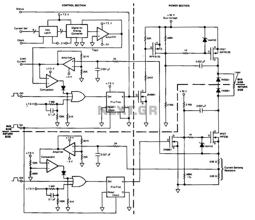
This circuit facilitates on/off switching, soft starting, current monitoring, current tripping, and overcurrent protection for a 30 Vdc power supply, accommodating normal load currents of up to 2 A. The switch is activated by an "on" command pulse and...
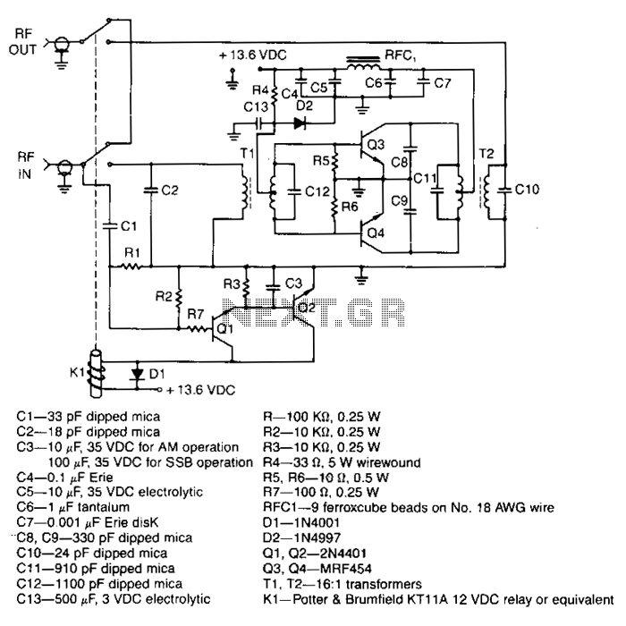
This amplifier delivers a nominal output power of 140 watts peak envelope power (PEP) when fed with input levels as low as 3 watts. Both the input and output transformers feature a 4:1 turn ratio and a 16:1 impedance...
This appears to be an infrared (IR) transmitter. IR signals do not penetrate walls, and it is assumed that this device is intended for use in a room separate from the one in which the user is located, rendering...

The following circuit is a power amplifier circuit for an FM transmitter with an output power of 30 watts. The power amplifier circuit utilizes a power transistor of type 2SC1946A. The FM transmitter operates with a 13.8-volt DC power...
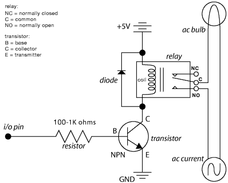
A circuit that allows a microcontroller to toggle a GPIO pin for shutting down the entire system, including the microcontroller itself. The system is normally powered down. When a momentary button is pressed by the user, power is restored....
Most Apple and Windows PCs can enter "sleep" or "standby" mode when not in use instead of being completely shut down. This mode allows the operating system to restore all previous work sessions within seconds upon waking via keyboard...