
1 Minute to 10 Minutes Adjustable Timer Circuit

The 555 timer IC is a versatile device widely used in various timing applications, including oscillators, pulse generation, and time delay circuits. In this adjustable timer circuit configuration, the 555 timer operates in monostable mode, meaning it produces a single output pulse in response to a trigger input.
When the circuit is powered on, the timing cycle begins. The timing interval is determined by the resistor-capacitor (RC) network connected to the 555 timer. Typically, a resistor (R1) and a capacitor (C1) are chosen based on the desired delay time. The formula for calculating the time period (T) is given by T = 1.1 × R1 × C1, where T is in seconds, R1 is in ohms, and C1 is in farads.
The green LED serves as a visual indicator of the timing process. It is connected to the output pin of the 555 timer, which goes high when the circuit is triggered, allowing current to flow through the LED, causing it to light up. This provides immediate feedback to the user that the timing operation is in progress.
At the end of the timing period, the output pin of the 555 timer returns to a low state, turning off the LED. This transition indicates that the timing cycle has completed. The adjustable nature of this circuit allows for changes in the timing duration by varying the values of R1 and C1, making it suitable for applications that require different timing intervals.
In summary, the 555 adjustable timer circuit is a simple yet effective solution for generating accurate time delays, with the added benefit of visual feedback through an LED indicator. This circuit can be utilized in various applications, such as timers, alarms, and automation systems.The 555 adjustable timer circuit starts timing when switched on. The green LED lights to show that timing is in progress. When the time period is over the.. 🔗 External reference
Related Circuits
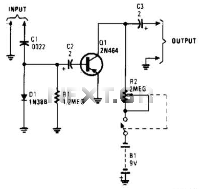
In this circuit, C1, D1, and R1 form an envelope detector. C2 couples audio to the base of Q1. R2 can be adjusted for the desired gain. The circuit under discussion utilizes an envelope detector, which is a fundamental component...
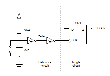
Building circuits to interface an Amiga A1200 to a PC AT/ATX power supply and tower case. To create a reliable interface between an Amiga A1200 and a PC AT/ATX power supply and tower case, it is essential to design a...

Using a power MOSFET, this amplifier can achieve a 2-W handheld radio power level, increasing it to approximately 10 W on the 2-meter band. A transmission-line RF switch is employed for transmit/receive (T/R) switching. The described amplifier utilizes a power...
The name of our game, LED Zeppelin, is a play on words. It comes not from the pop group of the same name but from Graf Von Zeppelin, a German who invented the first rigid air ship in 1900....
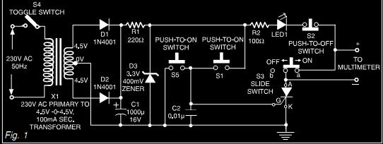
This document describes a simple triac tester circuit that can also be utilized for testing silicon-controlled rectifiers (SCRs) and both PNP and NPN transistors. The circuit operates on 3V DC, which can be derived from a Zener diode combined...
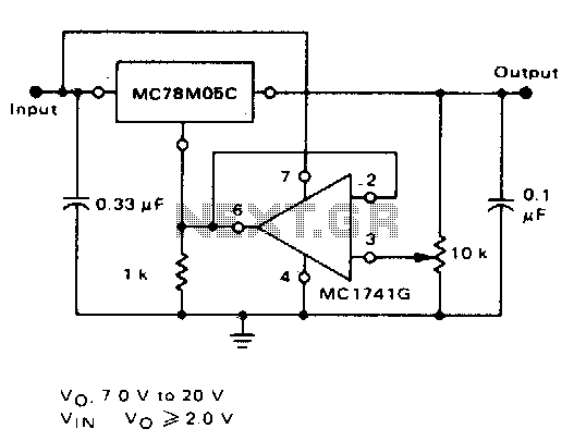
The inclusion of an operational amplifier facilitates the adjustment to higher or intermediate voltage levels while maintaining regulatory characteristics. The minimum voltage achievable with this configuration is 2 volts above the regulator voltage. The circuit employs an operational amplifier (op-amp)...