
Tuned-base Armstrong oscillator

The Armstrong oscillator circuit is characterized by its simplicity and effectiveness in generating oscillations. The key components include the transistor (Q1), the resonant tank circuit formed by L1 and C1, and the coupling capacitor (C2) that provides the necessary feedback for sustained oscillation. The resonant frequency of the oscillator is determined by the values of L1 and C1, which can be adjusted to achieve the desired frequency of operation. The regenerative feedback mechanism is critical for maintaining oscillation, as it ensures that energy lost during each cycle is replenished, preventing the oscillations from dying out.
In practical applications, the Armstrong oscillator can be used in various radio frequency (RF) applications, such as signal generation in transmitters and as a local oscillator in receivers. The design can be further optimized by selecting components with appropriate voltage ratings, current capacities, and frequency responses to ensure reliable operation in the intended application. Additionally, the circuit may be enhanced with additional stages of amplification or filtering to improve signal quality and stability. Overall, the Armstrong oscillator remains a foundational circuit in electronic design, illustrating the principles of feedback and resonance in oscillator design.The circuit in view (D) has all three requirements for an oscillator: (1) amplification, (2) a frequency-determining device, and (3) regenerative feedback. The oscillator in this schematic drawing is a tuned-base oscillator, because the fdd is in the base circuit.
If the fdd were in the collector circuit, it would be a tuned-collector oscillator. The circuit in view (D) is basically an Armstrong oscillator. Refer to figure 2-10, view (D), for the following discussion of the circuit operation of the Armstrong oscillator. When VCC is applied to the circuit. a small amount of base current flows through R2 which sets the forward bias on Q1. This forward bias causes collector current to flow from ground through Q1, R1, and L1 to +VCC. The current through L1 develops a magnetic field which induces a voltage into the tank circuit. The voltage is positive at the top of L2 and C1. At this time, two actions occur. First, resonant tank capacitor C1 charges to this voltage; the tank circuit now has stored energy. Second, coupling capacitor C2 couples the positive signal to the base of Q1. With a positive signal on its base, Q1 conducts harder. With Q1 conducting harder, more current flows through L1, a larger voltage is induced into L2, and a larger positive signal is coupled back to the base of Q1.
While this is taking place, the frequency-determining device is storing more energy and C1 is charging to the voltage induced into L2. The transistor will continue to increase in conduction until it reaches saturation. At saturation, the collector current of Q1 is at a maximum value and cannot increase any further. With a steady current through L1, the magnetic fields are not moving and no voltage is induced into the secondary.
With no external voltage applied, C1 acts as a voltage source and discharges. As the voltage across C1 decreases, its energy is transferred to the magnetic field of L2. Now, let`s look at C2. The coupling capacitor, C2, has charged to approximately the same voltage as C1. As C1 discharges, C2 discharges. The primary discharge path for C2 is through R2 (shown by the dashed arrow). As C2 discharges, the voltage drop across R2 opposes the forward bias on Q1 and collector current begins to decrease. This is caused by the decreasing positive potential at the base of Q1. A decrease in collector current allows the magnetic field of L1 to collapse. The collapsing field of L1 induces a negative voltage into the secondary which is coupled through C2 and makes the base of Q1 more negative.
This, again, is regenerative action; it continues until Q1 is driven into cutoff. When Q1 is cut off, the tank circuit continues to flywheel, or oscillate. The flywheel effect not only produces a sine-wave signal, but it aids in keeping Q1 cut off. Without feedback, the oscillations of L2 and C1 would dampen out after several cycles. To ensure that the amplitude of the signal remains constant, regenerative feedback is supplied to the tank once each cycle, as follows: As the voltage across C1 reaches maximum negative, C1 begins discharging toward 0 volts. Q1 is still below cutoff. C1 continues to discharge through 0 volts and becomes positively charged. The tank circuit voltage is again coupled to the base of Q1, so the base voltage becomes positive and allows collector current to flow.
The collector current creates a magnetic field in L1, which is coupled into the tank. This feedback action replaces any lost energy in the tank circuit and drives Q1 toward saturation. After saturation is reached, the transistor is again driven into cutoff. The operation of the Armstrong oscillator is basically this: Power applied to the transistor allows energy to be applied to the tank circuit causing it to oscillate. Once every cycle, the transistor conducts for a short period of time (class C operation) and returns enough energy to the tank to ensure a constant amplitude output signal.
Figure 2-11 🔗 External reference
Related Circuits
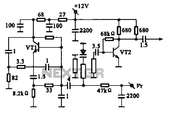
The local oscillator operates at frequencies of 1 GHz or higher, utilizing a common collector circuit, which makes it challenging to generate low-frequency self-oscillation. Typically, the local oscillator signal is passed through a buffer amplifier stage before being applied...
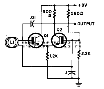
L1 is a loop consisting of 10 to 20 turns of insulated wire with a diameter ranging from 4 inches to 4 feet. The oscillator frequency, which operates between 7 to 30 MHz, varies significantly when an individual approaches...
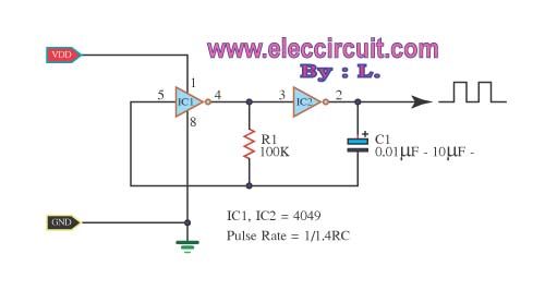
The inverter CMOS digital IC CD4049 is utilized to design a square wave oscillator generator. The CD4049 is a hex inverting buffer, which means it contains six independent inverters that can be used to generate square wave signals. This IC...
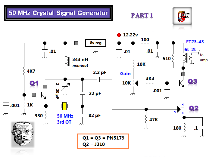
The initial tasks involved acquiring VHF components and investigating the Butler crystal oscillator, particularly focusing on the common base variant. The VHF knowledge base is rich with established information. There are claims that the emitter follower variant of the...
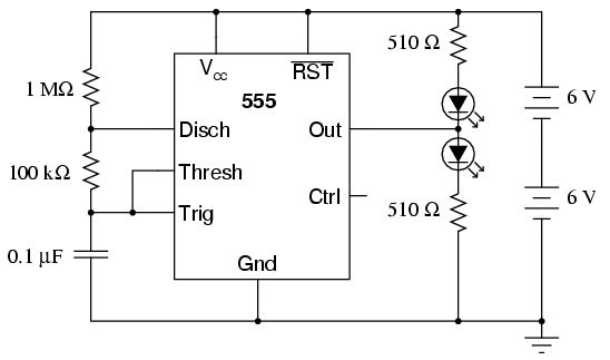
An oscilloscope is useful for analyzing the waveforms produced by this circuit, although it is not essential. An audio detector serves as a valuable piece of test equipment for this experiment, particularly if an oscilloscope is unavailable. The "555"...

A useful marker oscillator can be constructed using an NE555 timer to generate pulses at an audio frequency. This design facilitates the detection of the signal even amidst interference. The crystal frequency can range from 1 to 30 MHz. The...