
A DC power supply boost circuit

The DC booster circuit operates on the principle of increasing the voltage from a lower voltage source to a higher voltage output. This is accomplished through the use of a step-up transformer, which consists of primary and secondary windings. The primary winding is connected to the input voltage source, while the secondary winding delivers the boosted voltage to the load.
In this design, the transformer’s winding ratio plays a crucial role in determining the output voltage. By adjusting the number of turns in the primary and secondary windings, the desired voltage level can be achieved. For example, if the primary winding has 10 turns and the secondary has 20 turns, the output voltage will be double the input voltage. This flexibility allows for customization based on the specific requirements of the application.
Furthermore, the circuit can be modified to function as a voltage doubler. In this configuration, the circuit is designed to produce an output voltage that is twice the input voltage. This is particularly useful in scenarios where higher voltage levels are required, such as in powering certain types of electronic devices or circuits that demand more voltage than what is available from the power source.
The voltage doubler or tripler configurations involve additional components, such as capacitors and diodes, which are used to store and redirect the voltage effectively. These components work together to ensure that the output voltage is stabilized and meets the necessary specifications for the intended application.
Overall, the DC booster circuit is a versatile solution for applications requiring increased voltage, with the capability to be tailored to meet specific voltage needs through adjustments in the transformer winding ratio and circuit configuration.DC booster circuit shown in Figure flooded. Which is a step-up transformer circuit diagram, step-up transformer T can receive a small transistor radios changed rattan change the winding ratio according to the desired voltage. Figure 2 b is a voltage doubler circuit, if desired, also be designed as pressure MG} 3, 4 times the pressure circuit.
Related Circuits
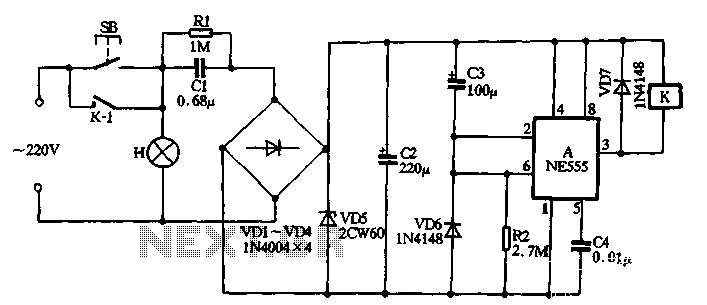
The NE555 push-button delay lamp circuit is illustrated in Figure 3-5. This circuit features several components, including a power supply and relay control system. Typically, the switch SB and normally open relay contacts K1 are in an open state,...

The circuit for the RS232 serial interface exhibits mild complexity. The primary components of the circuit include the 18F4520 microcontroller, MAX233A level shifter, and a DB-9 connector. This circuit utilizes a basic +5V power regulator to supply the digital...
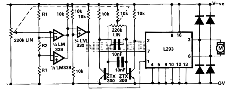
A limitation of the bi-directional proportional motor control circuit is that when the potentiometer is in its center position, the motor does not stop but continues to creep. This occurs due to the challenge of precisely adjusting the potentiometer...
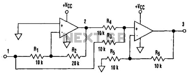
It is well understood that utilizing single-supply operational amplifiers (op amps) can present challenges when implementing simple functions in a bipolar signal environment. Often, this necessitates the use of additional op amps and other electronic components. Considering this, it...
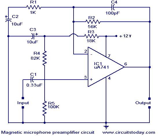
A preamplifier for magnetic pickups of record players is presented. The uA 741 is utilized as an AC-coupled non-inverting amplifier operating on a single supply. The amplifier gain is determined by the feedback components, where C2 manages the low-frequency...
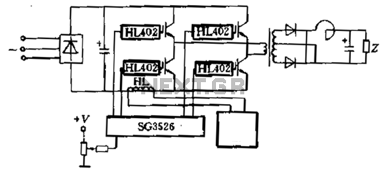
Applications are provided to complete the four-piece HL402 switching power supply system diagram, which drives four power IGBT switching power supplies. The IGBT drive pulse is generated by the SG3526. The HL component serves as a current sensor, utilized...