
Electronic Canary circuit

The modified Hartley oscillator is a type of electronic oscillator that generates a continuous waveform, typically a sine wave, using an LC (inductor-capacitor) circuit. The fundamental operation of the Hartley oscillator relies on the feedback mechanism provided by the inductors and capacitors to sustain oscillations.
In this configuration, the circuit includes two inductors (L1 and L2) and a capacitor (C). The inductors are connected in series, and the feedback is taken from the junction between them. The oscillation frequency can be determined using the formula:
\[ f = \frac{1}{2\pi \sqrt{(L1 + L2)C}} \]
Where \( f \) is the frequency of oscillation, \( L1 \) and \( L2 \) are the values of the inductors, and \( C \) is the capacitance.
To implement this oscillator as a doorbell, the output can be connected to a small speaker or piezoelectric buzzer to produce sound. The circuit may also include a transistor to amplify the output signal, ensuring that the sound produced is loud enough to be heard clearly.
Additional components may include a power supply, typically a battery or DC power source, and a switch to activate the oscillator when someone presses the doorbell button. The oscillator's frequency can be adjusted by varying the values of the inductors and capacitor, allowing customization of the sound produced to suit personal preferences.
This versatile circuit not only serves as a doorbell but can also be used in various applications where sound generation is required, making it an excellent choice for hobbyists and electronics enthusiasts.Feeling chirpy? Attract new friends with this modified hartley oscillator. You could also use it as a replacement doorbell.. 🔗 External reference
Related Circuits
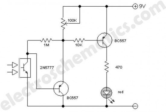
This enhanced infrared detector is designed for use with commercial infrared remote control handsets. This compact circuit is effective for quick go/no-go applications. The infrared detector circuit is engineered to respond to signals emitted by infrared remote control devices, commonly...
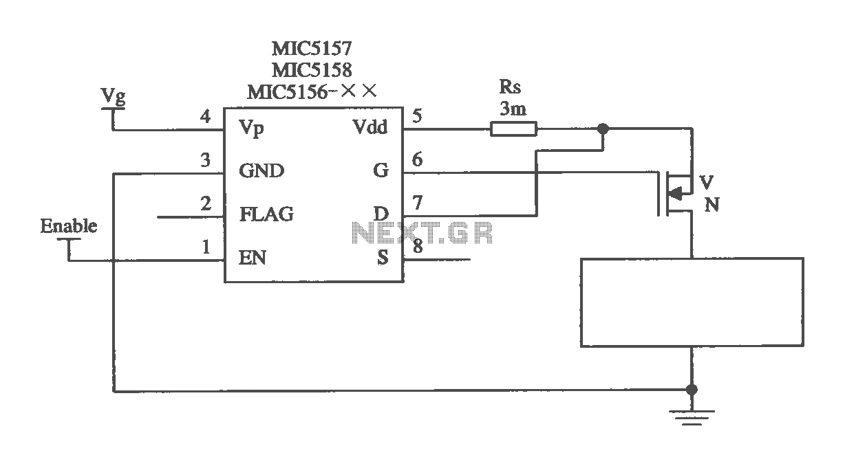
The MIC5156 is a device that incorporates a current limiting function, allowing it to handle high output currents. It can operate with or without a switching regulator circuit. The S terminal is left vacant, and a 16V Zener diode...
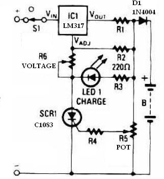
This schematic circuit for a battery charger consists of very few components but operates effectively. When power is applied to the circuit, SCR1 remains off, preventing any bias current from flowing to ground. The LM317 voltage regulator is connected...
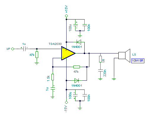
Connecting two TDA2030 through inexpensive power transistors allows for the creation of an amplifier capable of delivering higher power. This can be achieved by utilizing the component values specified in the schematic. To implement this circuit, two TDA2030 integrated circuits...
The RF power amplifier circuit described here utilizes the transistors 2SC1970 and 2N4427. This FM RF amplifier operates within the frequency range of 88-108 MHz, delivering an output power of approximately 1.3W from an input driver of 30-50mW. The...
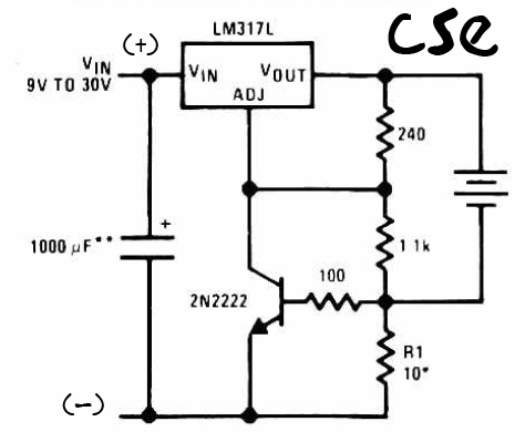
This is a straightforward charger designed for 9V to 30V batteries, primarily operated by the IC LM317L and a 2N222 transistor. It utilizes direct input DC voltage, and a recommended capacitor of 1000µF is included for filtering the output...