
Turning analog inputs into multi-switch digital inputs

In this project, the interactive LED game board or sci-fi prop is designed to enhance user experience through touch-sensitive tiles. Each tile, equipped with either a white LED or an RGB LED, will be controlled using a simple on/off mechanism. The proposed architecture involves a parallel resistor network, where each resistor corresponds to a specific voltage drop when a switch is pressed. This voltage drop is detected by an analog input, allowing the microcontroller to determine which switch has been activated based on the resulting voltage level.
The arrangement of resistors should be carefully calculated to ensure that the total voltage range aligns with the microcontroller's analog input specifications. Assuming a typical 5V system, the resistors can be selected to provide distinct voltage levels corresponding to each switch. For instance, a series of resistors could be configured to produce voltages of 0.5V, 1.0V, 1.5V, and so forth, up to the maximum voltage limit that the microcontroller can interpret. This method effectively allows for a compact input system, where a single analog input can manage multiple switches.
In a practical implementation, the microcontroller's firmware would include a routine to read the analog input and determine which switch is pressed by comparing the voltage level against predefined thresholds. Additionally, the firmware could be designed to handle multiple simultaneous switch activations by employing techniques such as voltage averaging or more complex algorithms that can differentiate between overlapping voltage signals.
To construct the circuit, the resistors should be connected in parallel with each momentary switch, ensuring that pressing a switch alters the voltage at the analog input. The circuit would also require a common ground connection and a power supply that matches the microcontroller's operating voltage. The LEDs would be connected to digital outputs on the microcontroller, allowing them to illuminate based on the detected input.
This design not only simplifies the control of multiple tiles but also minimizes the number of required microcontroller pins, making it feasible to create a large interactive display with a relatively small footprint. The project demonstrates the versatility of analog input systems in creating engaging interactive devices, paving the way for innovative applications in gaming and educational tools.I am interested in creating an interactive LED gameboard of some kind (or even a sort of "Stargate" DHD-type sci-fi prop!), where each square or tile is lit up from below by either a single white LED or an RGB combo. It always occurred to me that I`d love it if I could have each tile be responsive to touch. Nothing fancy, just a simple on/off switch. But the project I have in mind would either be 21 RGB tiles or 64 white or monochromatic ones. and that`s a lot of controllers! If I assemble a set of resistors, each selected to resist a discrete percentage of the total analog input voltage, and connect each resistor to a momentary switch, and put them all in parallel on the same analog input circuit, then each switch would lower the voltage by a different amount, and (with the right code, of course) that could be properly interpreted as the depression of that switch, and (for example) the appropriate LED could be illuminated! In other words, for example, if I have switches labeled A through H, and switch A allows the analog input to receive 0.
5V, and switch B allows the analog input to receive 1. 0V, and so on all the way up to H, which provides 8. 0V to the analog input, then it should be simple to write code that interprets each of these discrete voltage amounts as "representing" the depression of a particular switch, so that the rest of the code can respond appropriately. In fact, theoretically, if I come up with the right combination of resistors for each "column" of switches, I could even arrange it so that you could press more than one switch at the same time, and the code would recognize that unique new aggregate resistance properly as the combination of certain depressed switches!
However, even if you *could* only press one button at a time - and that certainly would be easier - that`s still a way to, for example, turn 8 analog inputs into 64 digital inputs! That`s enough to create a fully interactive, light-up chessboard with only an LED64 controller and a single 8/8/8 controller (you could use the other I/O connections for things like GAME SELECT and RESET and whatnot!), or to create a Stargate dialing device, where the tiles light up and unique SFX are triggered as you press them down.
That trick definitely works. I rigged up a system similar to what you`re talking about back when I was in college. I was using a 68HC11 dev board, not an 8/8/8, but the concept is the same. I had no real reason for doing this, I think I was just struck by the idea and wanted to try it. For each button, I used a precision multiturn potentiometer to create a voltage divider that could be tuned to a very specific voltage. I only ended up using five of them on one A/D input, but I`m sure you could cram a lot more in there.
Since the 8/8/8 has 10-bit inputs, you could theoretically increment each button by 5 mV and put 1023 switches on each analog input! Actually, the 0-1000 limitation in the Phidget system would limit you somewhat, but you get the idea.
Realistically though, I bet you could get 20 switches to work reliably on one input without much trouble. Now the problem of identifying multiple buttons simultaneously in a system like this, that`s a tough one.
For that you`ll need to consult someone who has much more free time than I do. Hey, I`m actually working on a project (FINALLY!) that`s using the principle I describe at the top, but now that I actually have the LCD / 8/8/8 unit, I see that the Analog Input has 3 contacts: +5V, ANALOG INPUT and GROUND. Even the diagram for hooking up a simple potentiometer shows that all three contacts are used. I`m afraid my electronics skills are insufficient for me to grasp the concepts, so. if I wanted to build the circuit I describe above, and I just want to use simple resistors (instead of pots that have voltage dividers with which I could hook up to all 3 contacts), so
🔗 External reference
Related Circuits
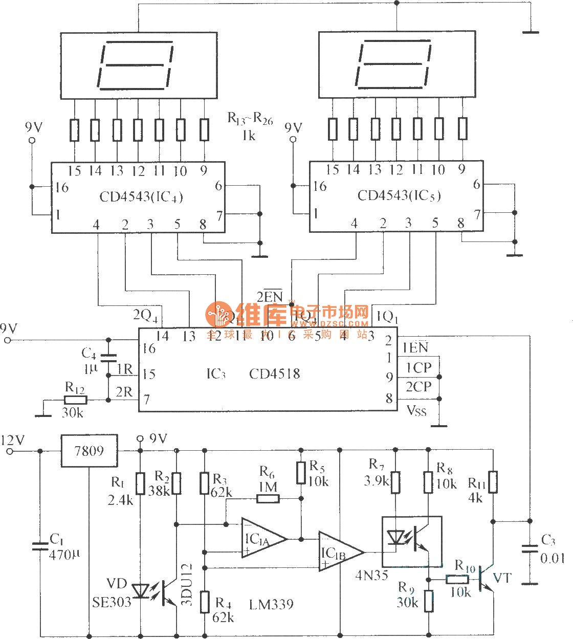
The circuit includes an optical input circuit (VD, 3DU12), a pulse forming circuit (IC1A, IC1B functioning as a voltage comparator; optical coupler; transistor switching circuit), and a counting and display circuit. The circuit architecture consists of several key components that...
The circuit diagram for a multiple output digital camera power supply using the MAX1802 is illustrated below. The MAX1802 chip features two buck converters and three boost converters. It accepts an input voltage range of 2.5 to 11V and...
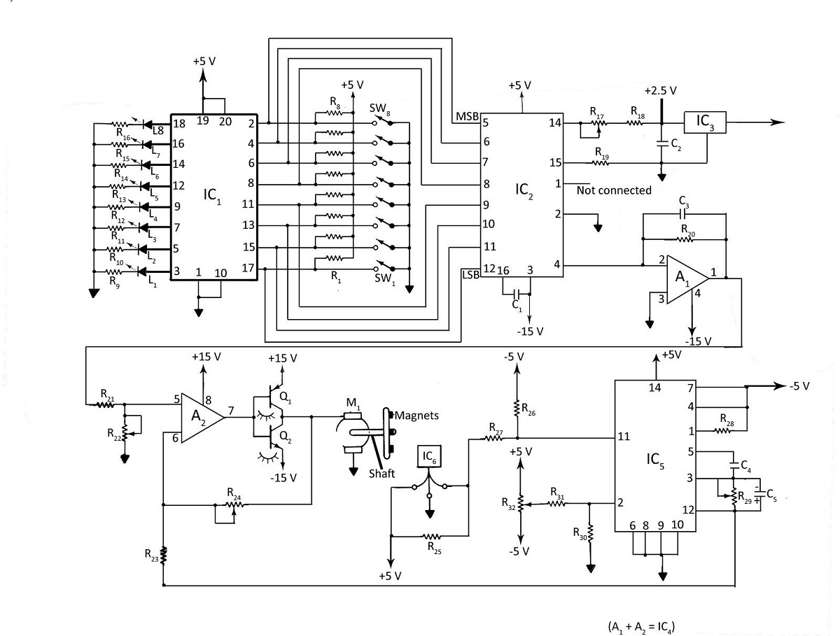
Various techniques can be employed to control the speed of a DC motor, including phase-locked-loop principles, digital inputs, or analog inputs. Additionally, the motor's speed can be monitored using LED or LCD displays. The digital DC motor speed controller...

This circuit is designed for differential analog circuit switches. The FM1208 monolithic dual differential multiplexer is utilized in applications where the RDS (ON) must be closely matched. The RDS (ON) for the monolithic dual multiplexer operates with a precision...
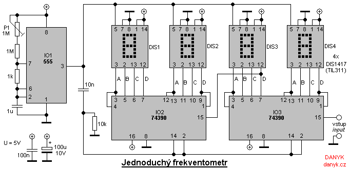
A simple digital frequency meter has various applications, serving as an experiment for beginners, laboratory equipment, or a meter integrated into certain devices. It is ideal for situations where frequency measurement and digital display are required. The frequency meter...
This chapter shows how to connect an analogue signal to a PIC. An analogue signal is similar to a sine wave and is generally less than 5v (5,000mV) in amplitude. Low-level signals are generally expressed in mV, to make...