
Turning gear from idling stop circuit diagram

The described circuit involves a gear lathe system where a limit switch (XWK) plays a critical role in controlling the operation of the motor through an AC contactor (coil C). When the turning clutch is engaged in the stop position, the limit switch is activated, interrupting the current flow to the contactor coil. This results in the immediate deactivation of the motor, ensuring that the lathe is safely unloaded from the stop line.
In terms of the schematic, the limit switch XWK is connected in series with the AC contactor coil C. The AC supply feeds into the contactor, and the limit switch acts as a safety mechanism to prevent accidental motor operation when the lathe is not in use. The circuit may also include additional components such as fuses for overcurrent protection and indicators for operational status.
The functionality of this circuit is essential for maintaining safety and operational efficiency in a lathe system. By ensuring that the motor can only be powered when the clutch is in the appropriate position, the design minimizes the risk of injury and equipment damage. Proper labeling of components and adherence to electrical standards is crucial for the successful implementation of this schematic in a real-world application. As shown in FIG gear lathe unloaded from the stop line. When turning clutch in the stop position, the limit switch XWK is breaking, AC contactor coil C power immediately, stop the motor. Such load can be achieved from the stop.
Related Circuits
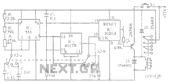
The system operates between 10 minutes to 2 hours, featuring a 100-line bell controlled by a multi-gear stick labeled S2 41f. The integrated circuit (IC) functions as a self-excited multivibrator. The device can manage binary pulses ranging from 3...
The ultrasonic signal received by the reception sensor is amplified by a factor of 1000 (60 dB) using a two-stage operational amplifier. The first stage provides a gain of 100 (40 dB), while the second stage offers a gain...
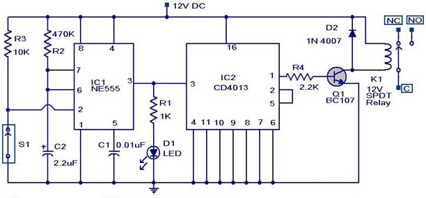
This weblog discusses electronic circuit schematics, PCB design, DIY kits, and electronic project diagrams. The circuit diagram presented is for a magnetic proximity switch, which has numerous applications across various fields. The circuit utilizes a magnetic reed switch (S1)...
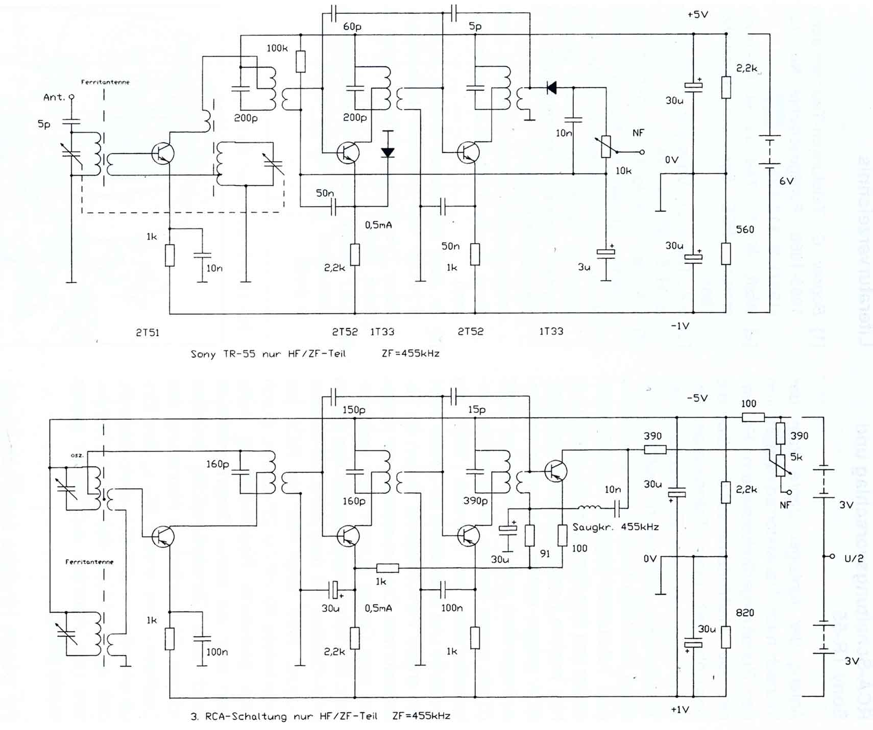
The circuitry of the Regency exhibits several unique characteristics. Notable features include the self-oscillating mixer stage, the base bias voltage of the second IF stage derived from the AF power stage, an unusual IF frequency of 262 kHz, and...
LED sequencer that follows the rhythm of music or speech, powered by a 9V battery, is a portable unit. The basic circuit illuminates up to ten LEDs in sequence, following the beat. The LED sequencer circuit operates by detecting audio...
This circuit is designed to indicate when room noise exceeds a predetermined threshold, utilizing a flashing LED to signal this condition. Three fixed noise levels are selectable: 50 dB, 70 dB, and 85 dB. The circuit employs two operational...