TV Antenna Amplifier Circuit
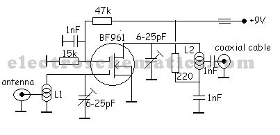
A simple and cost-effective TV antenna amplifier circuit is constructed using the BF961, a dual-gate N-channel MOSFET, which serves as the input and mixer stages.
The described TV antenna amplifier circuit utilizes the BF961 dual-gate N-channel MOSFET due to its high input impedance and low noise characteristics, making it ideal for amplifying weak TV signals received by antennas. The circuit is typically designed to enhance signal strength before it is processed by the television tuner, ensuring clearer reception of channels.
The BF961 operates in two stages: the input stage and the mixer stage. In the input stage, the antenna signal is fed into one of the gates of the MOSFET. The high input impedance of the BF961 allows it to efficiently couple with the antenna without significant signal loss. The gate configuration enables the circuit to amplify the incoming RF signals, providing a gain that can significantly improve reception quality.
In the mixer stage, the second gate of the BF961 is utilized to mix the amplified signal with a local oscillator signal, which can be generated by an additional circuit component. This mixing process converts the RF signals to an intermediate frequency (IF) that is more manageable for further processing. The output from the mixer stage can be connected directly to the TV tuner or to additional filtering stages to eliminate unwanted frequencies.
Power supply considerations are critical in this design. The circuit typically operates at low voltage, often between 5V to 12V, depending on the specific requirements of the application. Bypass capacitors may be included to stabilize the power supply and reduce noise, ensuring optimal performance of the amplifier circuit.
Overall, the simplicity and low cost of the BF961-based TV antenna amplifier circuit make it an attractive solution for enhancing TV signal reception, particularly in areas with weak signal strength. Proper layout and component selection will further optimize performance and reliability in practical applications.A very simple and cheap tv antenna amplifier circuit built with BF961 a NChannel Dual Gate MOS common transistor used for input and mixer stages especiall.. 🔗 External reference
