
TV audio circuit diagram TDA1521

The TDA1521 integrated circuit is designed for audio amplification applications, particularly in configurations that utilize an output transformerless (OTL) approach. This amplifier is capable of delivering high-quality audio signals with low distortion, making it suitable for consumer audio equipment. The pinout configuration provides essential connections for both input and output signals, as well as power supply requirements.
Pin 1 serves as the reverse input for the left channel, allowing the circuit to receive audio signals. Pin 2 acts as the positive input for the left channel, where the audio signal is fed into the amplifier. Pin 3 is critical for reference voltage management, ensuring the amplifier operates within the correct voltage range depending on the connection type—either OCL (output capacitor-less) or OTL.
The output for the left channel is provided at Pin 4, which delivers the amplified signal to the speakers. Pin 5 connects to the ground, serving as the negative power supply input in OTL configurations, which is essential for circuit stability and performance.
For the right channel, Pin 6 provides the output signal, while Pin 7 connects to a 22V positive power supply, which is necessary for proper amplifier operation. Pins 8 and 9 serve similar functions as their left channel counterparts, with Pin 8 being the positive input for the right channel and Pin 9 acting as the reverse input.
Overall, the TDA1521 is a versatile audio amplifier that can be effectively utilized in various audio applications, delivering reliable performance and high-quality sound reproduction. Proper understanding of its pin configuration and voltage requirements is crucial for effective circuit design and implementation. Colour is often used as shown in audio circuit (TDA1521), the circuit is taken from Changhong C2191, the OTL two-channel connection. TDA1521 pin functions and reference voltage : Pin 1: 11V-- reverse input 1 (L-channel signal input) Pin 2: 11V-- positive input 1 3 feet: 11V-- Reference 1 (when the OCL connection to 0V, when the OTL connection is 1/2Vcc) 4 feet: 11V-- output 1 (L-channel signal output) 5 feet: 0V-- negative power supply input (connection to ground when OTL) 6 feet: 11V-- output 2 (R channel signal output) Pin 7: 22V-- positive power supply input 8 feet: 11V-- positive input 2 9-pin: 11V-- reverse input 2 (R-channel signal input)
Related Circuits
Operating radio transmitters without a license is illegal in most countries, so caution is advised with transmitter circuits. This FM low-power circuit is designed to operate within the 87-108 MHz band II, providing a range of approximately 20 to...
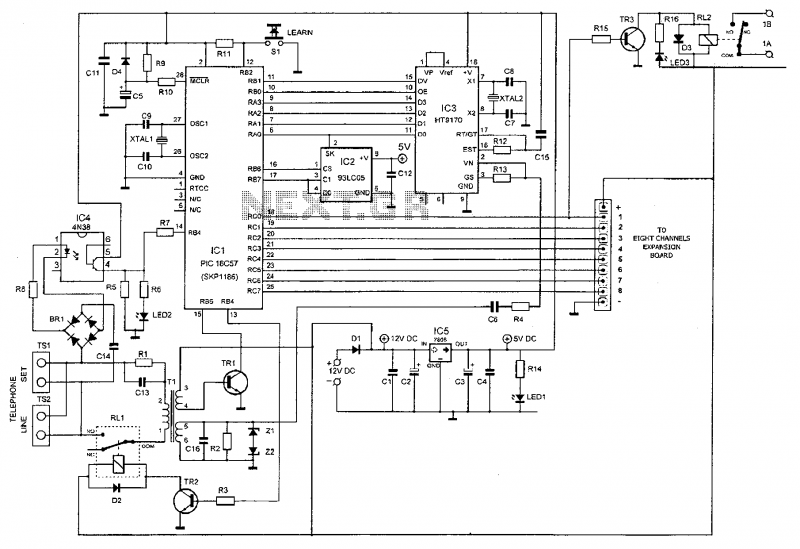
This device enables remote control of various appliances (up to eight with suitable add-on expansion boards) such as lights, water heaters, air conditioning, plant watering systems, alarms, etc., via a relay. It allows users to perform actions such as...
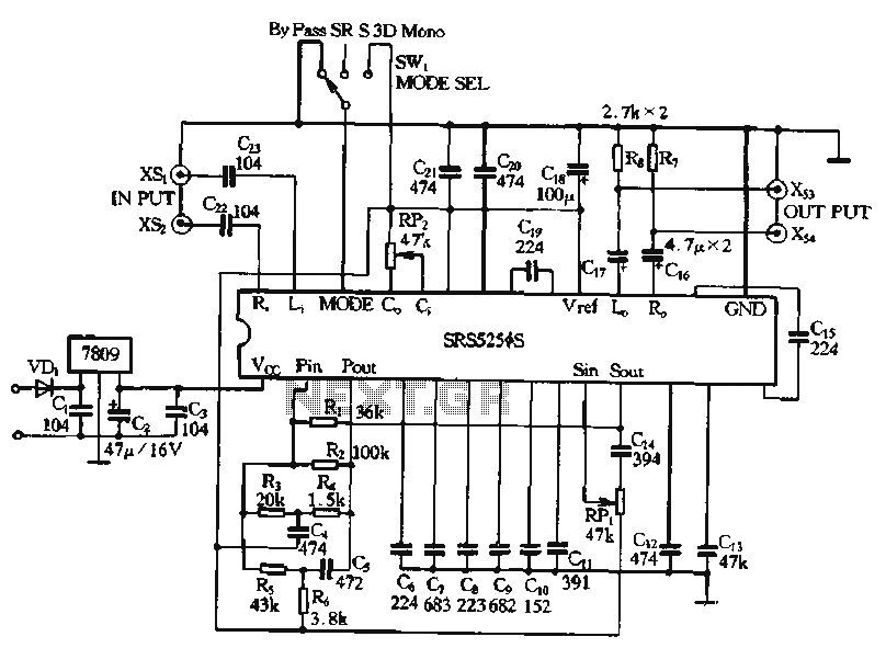
Typical application circuits for the Zheng brick SRS5250S are illustrated in the provided diagram. The SRS5250S features a pin diagram and a processing circuit that allows the user to switch between three operating modes: straight, SRS, and single-channel analog...
The Wireless Keylogger consists of two main building blocks: the transmitter and the receiver. The actual keylogging takes place in the transmitter, which is in fact a PS/2 hardware keylogger, with a built-in 2.4 GHz wireless module. Captured keystroke...
Many RC oscillators utilize advanced circuits within the phase shift unit. These circuits employ voltage feedback amplifiers, whose gain decreases significantly at high frequencies and ceases when high frequency is not attained. The variation in the phase characteristics of...
The schematic for this project is significantly more complex than previous designs. There are four primary features in the design: (1) the ability to program the PIC microcontroller on the developed board, (2) control of a servo motor, (3)...