
Tv modulator
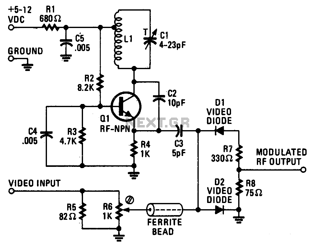
The described circuit employs a tuned Hartley oscillator to generate VHF frequencies, which are critical in various communication applications. The oscillator consists of a transistor, typically a bipolar junction transistor (BJT), which is biased by resistors R2, R3, and R4. The configuration of these resistors ensures that the transistor operates in the active region, enabling efficient amplification of the oscillation signal.
The tank circuit, composed of the tapped inductor L1 and the trimmer capacitor C1, plays a crucial role in determining the oscillation frequency. The trimmer capacitor allows for fine-tuning of the frequency output, facilitating adjustments based on specific application requirements. Capacitor C2 is strategically included in the design to provide positive feedback, enhancing the oscillation process by feeding back a portion of the output signal to the emitter of transistor Q1.
Capacitor C4 serves as an RF ground for the base of Q1, which is essential for stabilizing the oscillator's operation and minimizing unwanted noise. The inclusion of bypass capacitor C5 and resistor R1 is critical for filtering out any unwanted radio frequency interference that may be generated within the tank circuit. This filtering prevents potential radiation from affecting the power supply lines, thereby ensuring the integrity of the circuit's performance.
The video signal processing section of the circuit utilizes a parallel combination of resistors R5 and R6 to achieve impedance matching with standard 75-ohm video cables. This impedance matching is vital for minimizing signal reflections and ensuring optimal signal transmission. Resistor R6, configured as a small screwdriver-adjusted potentiometer, allows for precise control of the video input level before it is fed into the mixer diodes D1 and D2. This arrangement facilitates effective mixing and processing of the video signal, contributing to the overall functionality of the circuit in video applications.The VHF frequency is generated by a tuned Hartley oscillator circuit. Resistors R2, R3, and R4 bias the transistor, with tapped inductor LI and trimmer capacitor Cl forming the tank circuit. Adjusting Cl determines the frequency. Capacitor C2 provides positive feedback from the tank circuit to the emitter at Q1. Capacitor C4 provides an RF ground for the base of Ql. Bypass capacitor C5 and resistor Rl filter out the radio frequencies generated in the tank circuit to prevent radiation from the power-supply lines
The video signal enters the parallel combination of resistors R5 and R6; this combination closely matches the 75 ohm impedance of most video cables. Resistor R6 is a small screwdriver-adjusted potentiometer that is used to control the video input level to mixer diodes Dl and D2.
🔗 External reference
Related Circuits
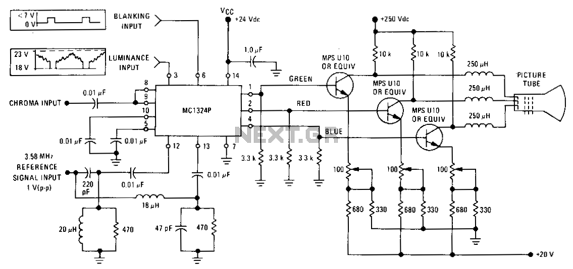
The MC1324 provides chroma demodulation, recovering the R, G, and B signals to drive video amplifiers for each color difference signal. The luminance signal and chrominance signal are matrixed to obtain the R, G, and B signals. The MC1324 is...
The RF modulator is a crucial component in televisions, VCRs, satellite receivers, format converters, home computers, and gaming consoles. This circuit is straightforward, stable, and easy to construct, allowing for seamless integration with various circuit boards. The schematic diagram...
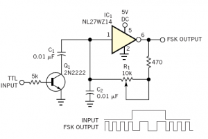
Audio frequency-shift keying (AFSK) is a modulation technique that represents digital data through variations in the frequency (pitch) of an audio tone, resulting in an encoded signal suitable for transmission via radio or telephone. Typically, the transmitted audio alternates...
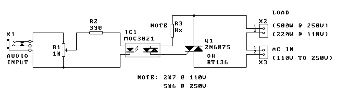
A music-to-light modulator is a circuit which controls the intensity of one or more lights in response to an audio input. The problem in older circuits is that there was a direct electrical connection between the lights using mains...
This circuit serves as an introduction to pulse-width modulation experimentation, utilizing a dual 555 timer for simplicity. A small PCB has been designed to facilitate construction. Although not an original design, it complements the "Dimmer with MOSFET" article on...

When a carrier signal is modulated using amplitude modulation, four frequency components are produced. The first component is the modulating signal itself, the second is the carrier frequency, while the last two are the sum and difference of the...