
TV remote control Blocker Circuit Jammer using Ic 555 and IR Leds

The circuit design incorporates a 555 timer IC, which is a versatile and widely used component in electronic circuits. In this configuration, the 555 timer operates in astable mode, producing a continuous square wave output at a frequency of approximately 38 kHz. This frequency is critical as it aligns with the typical modulation frequency of IR remote controls, allowing the device to effectively disrupt the communication between the remote and the TV.
The output from the 555 timer is utilized to drive an array of infrared LEDs. The transistor amplifies the current from the timer, ensuring that sufficient power is provided to the LEDs for effective operation. The choice of a 180-ohm resistor in the circuit is important; reducing its value increases the current flowing through the LEDs, thereby enhancing the range of the jamming effect. However, care must be taken not to lower the resistance below 100 ohms to prevent potential damage to the components.
The inclusion of a 4.7 kΩ potentiometer allows for fine-tuning of the device's output. By adjusting this potentiometer while aiming the device at the TV, the user can find the optimal setting that maximizes the jamming effect, effectively preventing the remote from functioning. This process may require several attempts to achieve the desired outcome, as the effectiveness can vary based on the specific TV model and its sensitivity to IR signals.
Overall, this circuit represents a straightforward yet effective approach to jamming infrared remote controls, utilizing common electronic components to achieve its functionality.Just point this small device at the TV and the remote gets jammed. The circuit is self explanatory. 555 is wired as an astable multivibrator for a frequency of nearly 38 kHz. This is the frequency at which most of the modern TVs receive the IR beam. The transistor acts as a current source supplying roughly 25mA to the infra red LEDs. To increase the range of the circuit simply decrease the value of the 180 ohm resistor to not less than 100 ohm. It is required to adjust the 4. 7K potentiometer while pointing the device at your TV to block the IR rays from the remote. This can be done by trial and error until the remote no longer responds. 🔗 External reference
Related Circuits
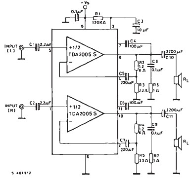
The TDA2005 car audio amplifier circuit is specifically designed for use in devices such as car radios and CD players. This amplifier circuit utilizes the TDA2005 audio integrated circuit (IC), which can deliver a maximum output power of 20...
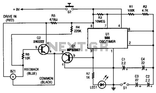
The electronic darkroom timer is constructed using a 555 oscillator/timer, a pair of general-purpose transistors, a buzzer, and an LED. The 555 timer (U1) is set up as an astable multivibrator, functioning as a free-running oscillator. The frequency of...
I have been researching a "mystery circuit" and I cannot determine its name. Assistance is requested. The inquiry pertains to an unidentified electronic circuit, often referred to as a "mystery circuit." Such circuits can encompass a wide range of configurations...
This circuit automatically controls the headlight of a motorcycle, turning it on and off independently of the light and ignition switches, as long as the battery is fully charged. The initial stage employs a 220-ohm resistor and ZD1 to...
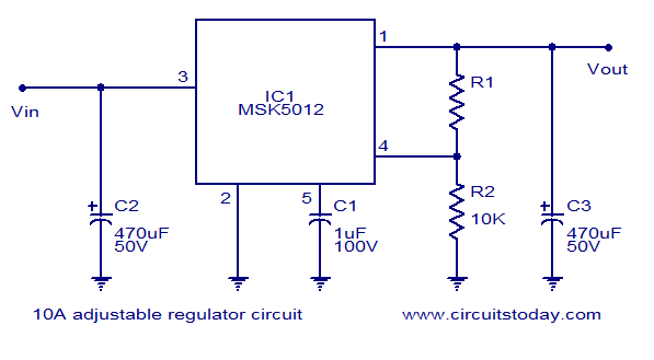
A reliable 10A adjustable voltage regulator based on the MSK5012, featuring an output voltage range of 1.3 to 30V. It is characterized by low ripple and high efficiency. The MSK5012 adjustable voltage regulator is designed for applications requiring a stable...
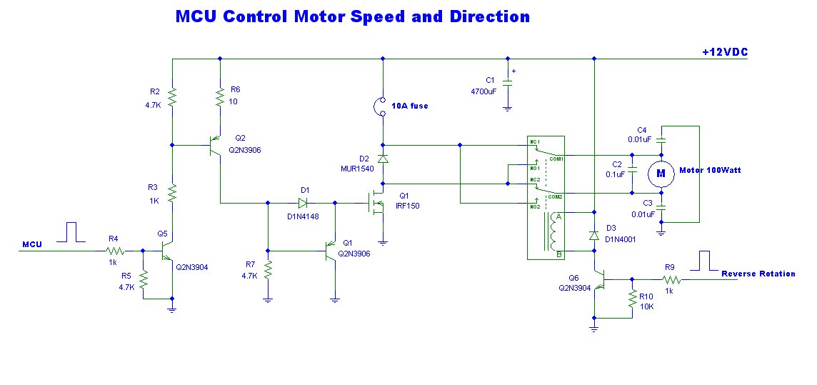
This is a power motor controller circuit designed for 12V applications. It utilizes a microcontroller unit (MCU) for signal control, operating at a high voltage level of approximately 3V. The circuit allows for the motor to be controlled to...