
What is the name of this OpAmp Circuit

The inquiry pertains to an unidentified electronic circuit, often referred to as a "mystery circuit." Such circuits can encompass a wide range of configurations and functionalities, making identification challenging without additional context or specifications.
To assist in the identification and analysis of the circuit, it is essential to gather details such as the circuit's schematic, components used, voltage and current ratings, and the intended application. Common types of circuits that may be considered "mystery circuits" include oscillators, amplifiers, timers, and various digital or analog signal processing circuits.
In many cases, the circuit may utilize standard components such as resistors, capacitors, diodes, transistors, and integrated circuits (ICs). Each component plays a critical role in the overall functionality. For example, resistors limit current, capacitors store and release energy, and transistors can act as switches or amplifiers.
When analyzing a mystery circuit, it is advisable to trace the connections between components, measure voltages at various points, and observe the behavior of the circuit under different conditions. Using simulation software can also aid in visualizing the circuit's operation and understanding its purpose.
In conclusion, identifying a mystery circuit involves a systematic approach to examining its components and behavior. With the right tools and methodologies, it is possible to uncover the circuit's name and functionality.Hey guys I`ve been researching a ""mystery circuit"" and I can`t figure out what its name is. It`s driving me crazy!!!! Please HELP ME!!! Thanx.. 🔗 External reference
Related Circuits
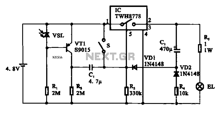
Automatic emergency lamp circuit featuring an electronic switch integrated circuit. This circuit is designed for automatic emergency lighting. The system operates based on ambient light conditions; when light levels are low at night, the circuit activates the emergency lamp....

A voltage comparator is a device that compares the voltages at its two inputs and generates an output based on the comparison. It produces a high output when the positive input exceeds the negative input and a low output...
This circuit functions as an RF power amplifier designed to operate with a power supply capable of delivering 13 volts at a current of 10 amperes. Careful assembly of the power source is essential. It utilizes a shielded transformer...
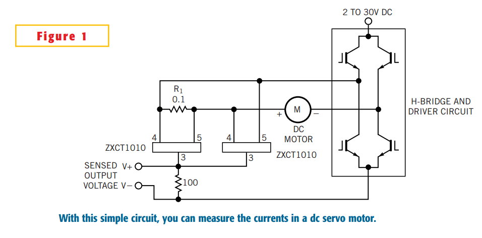
The simple circuit design in Figure 1 lets you measure all components of a current flowing in a dc servo motor. The rectified output of the circuit uses ground as a reference, so you can measure the output by...

Alarm system designs often require circuitry that can detect whether a phone line is active or broken. The primary challenge in this design is to draw less than 5 µA from the phone line, which operates within a voltage...
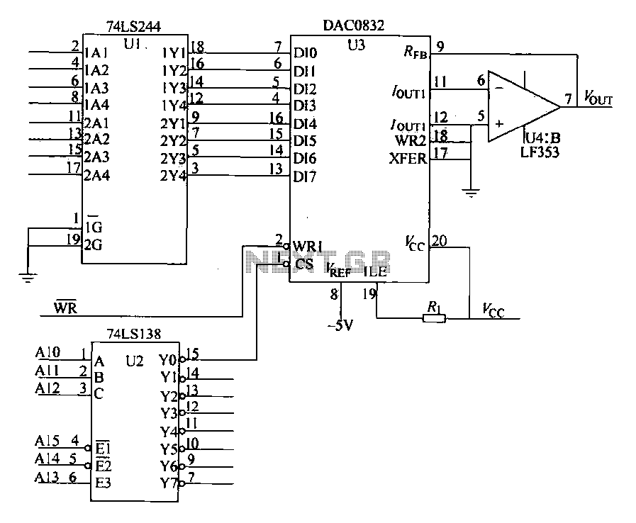
The DAC0832 is depicted in Figure 27-13 as a single-phase circuit connected to the 8086 CPU. The internal 8-bit data input of the DAC0832 must be interfaced with the CPU and the D/A converter interface circuits for data transmission,...