
Simple Siren Circuit

The described circuit employs a free-running multivibrator configuration utilizing both PNP and NPN transistors, which facilitates the generation of oscillating signals. The multivibrator's operation hinges on the charging and discharging cycles of capacitor C1, which is influenced by resistor R1. When switch S1 is engaged, the charging process of C1 introduces a time delay that is governed by the RC time constant, defined by the resistance of R1 and the capacitance of C1. As the voltage across C1 builds up to 4 volts, it effectively alters the timing characteristics at the junction of R2 and C2.
The RC circuit comprising R2 and C2 plays a critical role in modulating the frequency of the output signal. As the voltage at the junction decreases due to the charging of C1, the time constant at this point decreases, resulting in a higher frequency output from the multivibrator. This creates a rising tone characteristic of a siren. Conversely, once S1 is released, C1 begins to discharge, which increases the time constant at the R2/C2 junction, leading to a reduction in frequency and thus a falling tone.
The output waveform is a sawtooth shape, characterized by its linear rise and sudden drop, which effectively mimics the sound of a siren. This waveform can be further processed or amplified to drive speakers or other audio devices, enhancing the siren effect. The careful selection of resistor and capacitor values allows for tuning the frequency range and the duration of the rising and falling tones, making this circuit versatile for various applications where siren-like sounds are required.This circuit generates a tone that sounds very similar to a siren. The generator part of the circuit is made of the combination of PNP and NPN transistors. Toghether, the two transistors build up a free runing multivibrator. If the C2 capacitor was connected to the positive line of the power supply, it would have worked as a constant frequency osc illator. However, we dont want a constant frequency oscillator. We want a siren. So to generate an up and down going signal tone, the resistor R2 is fed from an RC circuit. When the switch S1 is pressed, the capacitor C1 charges via R1 slowly until it reaches the maximum voltage level of 4 volts. This increasing voltage results to a decreasing time constant at the R2/C2 junction. This furthermore results to an increasing frequency of the multivibrator. After the switch S1 is released, the capacitor C1 discharges slowly resulting to a decreasing frequency cycle.
Through the combination of the two time constants a sawtooth waveform is generated. 🔗 External reference
Related Circuits

This is a circuit design for an FSK demodulator, which is an electronic device that converts an FSK signal into a serial digital signal. FSK modulation is used to transmit digital serial data, and demodulation is necessary to retrieve...
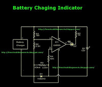
This is a battery charger indicator circuit diagram. When the battery is charging, it is indicated by an LED. This circuit can be used with a 12V battery with a charging current of less than 1A. The battery charger indicator...

This compact water sensor alarm circuit emits a loud warning sound when a humidity sensor detects the presence of water. The circuit utilizes the low-power comparator LM1801 from National Semiconductor. A fixed reference voltage for the integrated circuit is...
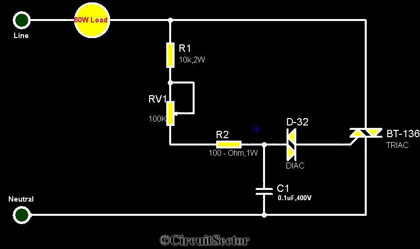
The circuit diagram presented is a triac-diac electronic fan regulator designed to reduce power consumption of electric fans, even at low speeds. Traditional resistor-inductor fan regulators tend to generate excess heat, wasting energy when the fan operates at lower...

Design a low-cost 4- to 20-mA receiver circuit for control loops using an analog-to-digital converter (ADC). The design of a low-cost 4- to 20-mA receiver circuit is essential in industrial applications for monitoring and controlling processes. This current loop standard...
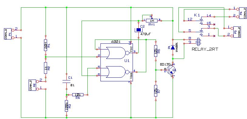
This is a simple alarm circuit using a CD4001 integrated circuit. It is designed for home, motorcycle, car, or other applications. The circuit will undergo computer simulation using Livewire, followed by printed circuit design with KiCad. SW1 is a...