
Battery Powered Infrared Remote Control Extender
The circuit operates based on a simple yet effective design that prioritizes low power consumption and adaptability for various environments. The integration of capacitors, resistors, and transistors plays a crucial role in ensuring the circuit's functionality and longevity. The use of capacitors, specifically C2, allows for energy storage, which is pivotal for powering the emitter diode during signal transmission. The choice of transistors impacts both the gain and the switching capabilities of the circuit, ensuring efficient operation even under varying conditions.
The inclusion of LEDs serves both functional and diagnostic purposes, providing visual feedback on the operational status of the circuit. The green LED indicates active transmission, while the yellow LED signals successful recharging of the capacitor. This dual-LED setup enhances user interaction and allows for quick troubleshooting.
To further enhance the circuit's resilience to ambient light interference, careful consideration of housing materials and designs is recommended. The opaque housing not only protects the internal components but also minimizes the potential for false triggering due to unwanted IR signals. The strategic placement of the receiver diodes and the use of filters or shading materials can significantly improve the reliability of the circuit, making it suitable for diverse lighting conditions.
The adaptability of the circuit to different power sources, including alkaline batteries and AA batteries, makes it versatile for various applications. The option for portability through the earphone socket allows for flexible usage across multiple locations, catering to different user needs.
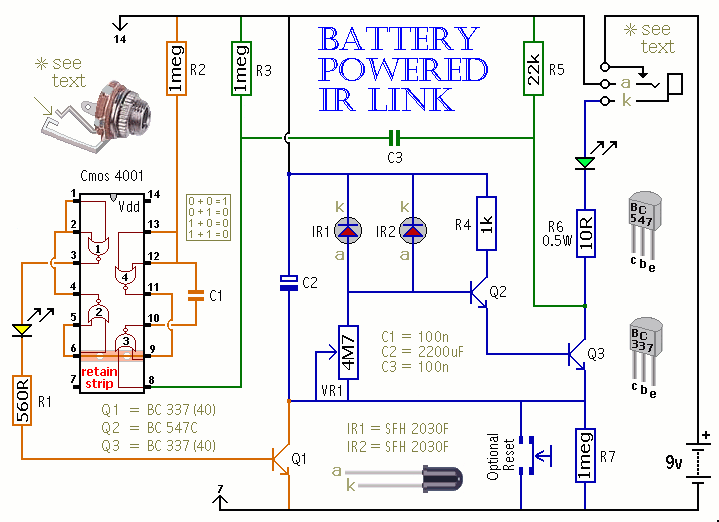
In summary, this battery-powered IR link circuit is a well-engineered solution for remote control applications, emphasizing low power consumption, effective signal transmission, and adaptability to environmental factors. The thoughtful design considerations contribute to its robustness and reliability, making it a practical choice for users seeking a dependable IR communication system.This is a battery powered IR Link which may be used in more than one room. The standby current is extremely low - so battery life is excellent. And by shutting down in the presence of extraneous IR radiation - it copes with the problem of excessive output current. This circuit is not powered directly from the battery. When a remote control signal is received - the energy stored in C2 - drives the emitter diode. At the same time - Q1 switches on briefly - and allows the battery to recharge C2. The green LED shows that the circuit is transmitting - and the yellow LED confirms that C2 has been topped-up. There is unwanted IR radiation in both daylight and tungsten lighting. To minimize its effect use an opaque housing and do not make the opening too large. (Try a horizontal slot measuring 2 cm X 1. 5 cm. ) Shade the receiver diodes by mounting them side-by-side a few centimetres deep - inside the case. The depth of shading required will depend on the lighting conditions. (Try 5 cm to start with). To reduce the effects of visible light - use receiver diodes with a built-in daylight filter ( Maplin CY91Y).
Or cover the opening using a small piece of dark transparent plastic. Part of the display panel from a scrap VCR is ideal. Position the unit out of direct light and avoid reflective surfaces. If all else fails, adjust VR1 to reduce sensitivity. What you are aiming for is to ensure that in standby mode Q2 remains switched off so that C2 retains its charge. If unwanted radiation does reach the receiver it will not result in a large output current. C2 simply discharges and the circuit shuts down. When the source of the unwanted radiation is removed the unit may be reset by interrupting the power supply for a few seconds or by pushing the (optional) reset button.
If you do neither then it will reset itself after about an hour when C2 has recharged through R7. With two receiver diodes wired in parallel, the operating range is up to about 1 meter. The exact distance depends on the remote you are using and on the position of VR1 (start by setting it about halfway). Correctly focused - a plastic lens from a small magnifying glass will extend the distance. I used the high gain version of the BC337 because that was what I had available. However, the only transistor whose gain is likely to be important is the BC547C. For the infrared emitter I used a TIL38 (Maplin YH70M) at the end of 12 meters of alarm cable. However, the diode from a scrap remote control should be worth trying also. Two diodes wired in series will give improved output performance. The circuit was designed with a small 9-volt alkaline battery in mind (PP3, MN1604, 6LR61) but the prototype worked well at 6-volts using four AA batteries.
The standby current was too small to measure reliably. An earphone socket makes the unit portable; so it can be used in more than one room. If you can obtain the style of socket in the diagram - (Maplin HF82D) - its normally closed switch can be converted to a normally open switch by releasing the inner contact as shown. This means that it will act as an on/off switch when you unplug the lead. And - because it allows you to interrupt the power supply - there`s no need for a reset button. 🔗 External reference
Related Circuits

The miniature transmitter module, measuring 34 mm x 29 mm x 10 mm, is designed to operate all remote control receiver-switch combinations outlined in this project. A compact 9-volt PP3 battery can be utilized with the transmitter, which is...
The first phase of a motion-controlled photography rig has been completed, focusing on the setup of bipolar stepper motor controllers. This component is crucial for motor control, which is essential for achieving motion in the project. A list of...

A bidirectional H-bridge DC motor control circuit is illustrated. The circuit utilizes the L298 integrated circuit from ST Microelectronics. The L298 is a dual full-bridge driver that supports a wide operating voltage range and can manage load currents up...
A method for measuring static electricity for a science project was sought. An old copy of "Getting Started in Electronics" by Forrest M. Mims III was referenced for guidance. To create a static electricity measurement circuit, a simple design can...
The circuit depicted can be utilized to control a unipolar stepper motor equipped with four coils. This design is derived from an older fax machine. The circuit is capable of handling a motor current of approximately 500 mA per...

In August 2007, an individual with a passion for photography acquired a Panasonic FZ30 digital camera and joined a forum on dpreview dedicated to Panasonic products. A fellow forum member, who was a programmer and electronics enthusiast, created a...