
TV signal amplifier 470Mhz-860Mhz

This RF amplifier circuit employs the BFQ34 transistor, which is suitable for low-noise amplification in RF applications. The Class A configuration ensures that the transistor operates in the linear region, providing consistent amplification without significant distortion when the input signal is within the specified range. The choice of a 10 mW input signal is optimal for achieving the desired gain while maintaining signal integrity.
The BFQ34 transistor, with its SOT122A package, allows for efficient thermal management and compact design, essential for RF applications where space is limited. The recommendation against using the BFQ34T variant is critical, as different transistor characteristics can lead to suboptimal performance or even circuit failure.
The power supply requirement of 12 volts and 1 amp is crucial for ensuring that the transistor operates correctly without entering saturation or cutoff regions, which would compromise the amplifier's performance. A regulated power supply is advised to maintain a stable voltage under varying load conditions.
To prevent signal distortion, it is imperative to monitor the input levels and ensure they do not exceed the specified limits. Overdriving the transistor can introduce unwanted harmonics and reduce the overall fidelity of the amplified signal.
Enclosing the circuit in a metal box serves multiple purposes, including shielding against electromagnetic interference (EMI) and providing physical protection for the components. The enclosure should be designed to allow for adequate ventilation to dissipate heat generated by the transistor during operation. Proper grounding techniques should be employed within the metal box to minimize noise and ensure reliable operation of the amplifier.This amplifier can amplify to 10dB the RF signal from antenna working as class A and is based on transistor BFQ34 of Philips. The transistor comes in case SOT122A. You may find the BFQ34T in market but better do not use it as it has different characteristics. Input signal should be about 10mW if we want 10dB output. So with 0.5mW we get 5dB. Do not overdrive the transistor because the signal will be distorted full of lines, without color etc. So use 12Volts with 1A stabilised power supply. The circuit should be enclosed in a small metal box.
Related Circuits

Gain increases by decades as the binary input decreases from 1,1 to 0,0. Minimum gain is 1 and maximum gain is 1000. More: Since the switch is static in this type of amplifier, the power dissipation of the switch...
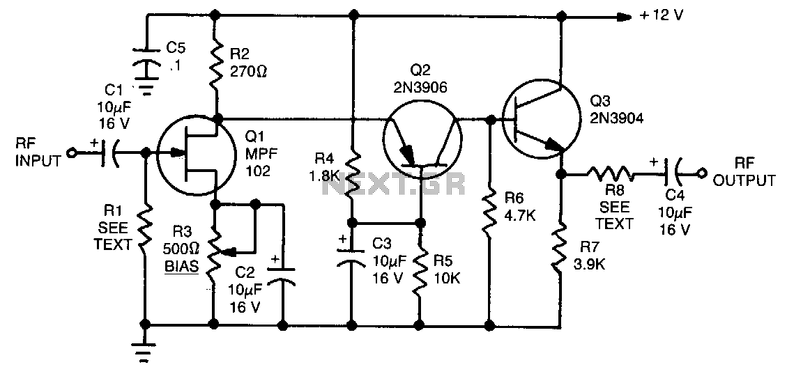
The circuit features a frequency response ranging from 100 Hz to 3 MHz, with a gain of approximately 30 dB. Field-effect transistor Q1 is configured in a common-source self-biased mode. An optional resistor R1 allows for the adjustment of...
Main Power Amplifier OCL 100 watt using MJ802 and MJ4502 transistors. It is designed to provide strong bass and bold treble, making it suitable for various applications such as parties or home theater systems. This Class AB amplifier delivers...
The sound quality was poor, and then it stopped functioning. Can anyone explain which part of the circuit may have malfunctioned? Any suggestions to enhance the sound quality and restore functionality? The transistors used are both BC546, and the...
LVDT (linear voltage differential transformer) is widely used as a linear position sensor. The AD589 integrated circuit provides a complete solution for LVDT. The Linear Voltage Differential Transformer (LVDT) is a highly precise sensor commonly employed for measuring linear displacement....
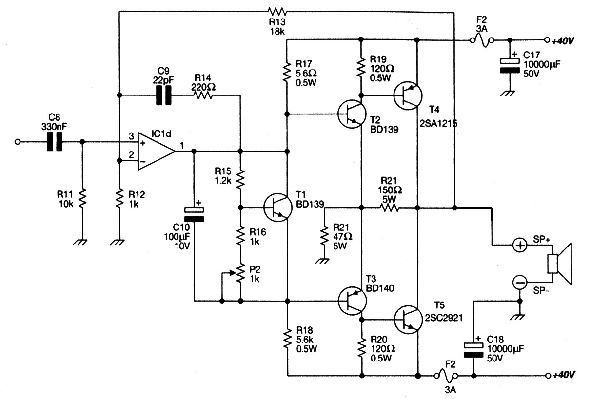
This design utilizes a well-established circuit topology for the power amplifier, employing a single-rail supply of approximately 60V and capacitor coupling for the speaker(s). The benefits for a guitar amplifier include a straightforward circuit design even at relatively high...