
TV STATION CONTROL

The described system involves a sophisticated method of utilizing control pulses during the blanking interval of a television signal. The blanking interval is a period when the transmission of visual information is paused, allowing for the synchronization of various components in the television system. During this interval, the transmitter can send control pulses that are not visible to the viewer but are crucial for managing the broadcast content.
Receiver circuits are designed to interpret these control pulses. The decoding process involves the use of specific electronic components, such as demodulators and microcontrollers, which work together to detect and translate the incoming signals. The output of this decoding process results in six different switching actions. Each of these actions corresponds to a distinct command that can trigger specific events in the broadcast, enabling the seamless integration of additional content.
For instance, one switching action might activate a commercial break, while another could display a weather report. This functionality allows network stations to customize their broadcasts, offering tailored content to their audiences. Furthermore, local film projector material can be introduced, enhancing the viewing experience with region-specific programming.
The flexibility and efficiency of this system are critical in modern broadcasting, where timely and relevant content delivery is essential. The ability to utilize blanking interval pulses for content switching not only optimizes the use of air time but also enhances viewer engagement by providing diverse programming options. Overall, this technology represents a significant advancement in the field of television broadcasting, allowing for greater control over the transmitted content.Control pulses transmitted in blanking interval by tv network transmitter are decoded by receiver circuits shown and translated into six different switching actions used to introduce special program matter such as commercials, weather reports, and local film projector material that may be different for each network station. -K. Kazama and T. Ishino , Remote Tv Control by Blanking-Interval Pulses, Electronics, 33:20, p 79-81. 🔗 External reference
Related Circuits
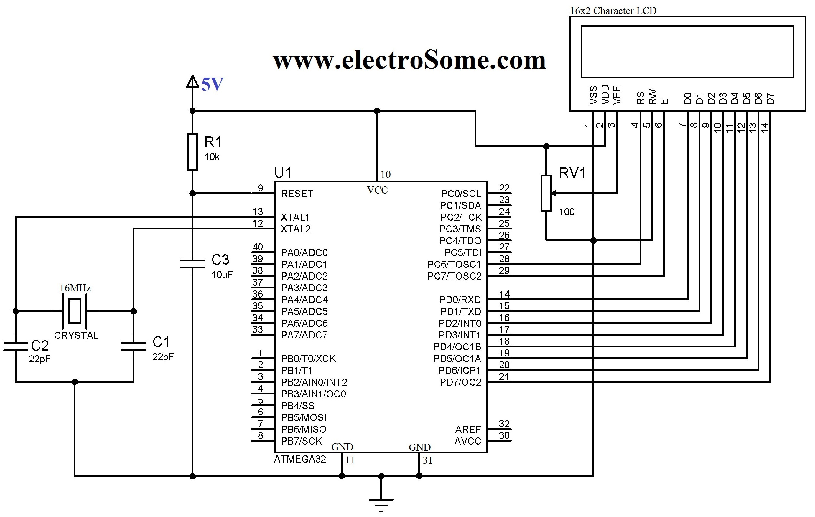
An LCD (Liquid Crystal Display) is a widely used electronic display found in devices such as calculators, laptops, tablets, and mobile phones. The 16G-2 character LCD module is a fundamental component frequently utilized by electronics enthusiasts and integrated into...
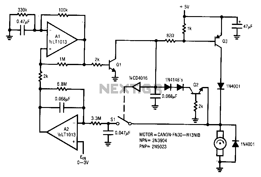
This circuit is particularly applicable to digitally controlled systems in robotic and X-Y positioning applications. By operating from a 5-V logic supply, it eliminates the need for additional motor drive supplies. The tachless feedback mechanism saves both space and...
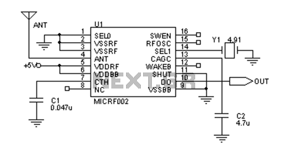
Early transmitters using LC oscillators experience significant frequency drift. The introduction of Surface Acoustic Wave (SAW) devices addresses this issue, providing substantial frequency stability comparable to crystals. These devices can achieve fundamental frequencies in the hundreds of megahertz or...
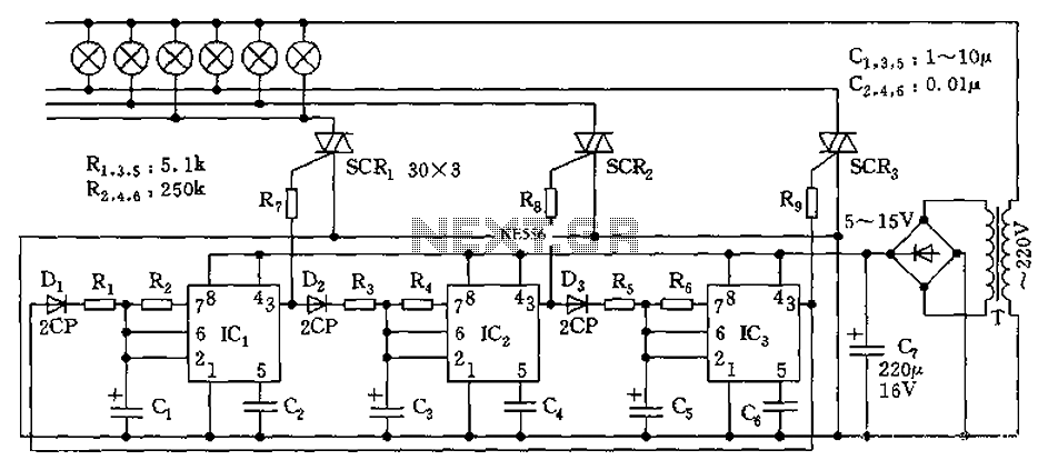
The circuit utilizes a 555 timer as its core component to control three lights through a cyclic trigger monostable delay circuit. The brightest light is controlled by a silicon-controlled rectifier (SCR) that determines the cycle of illumination. When pin...
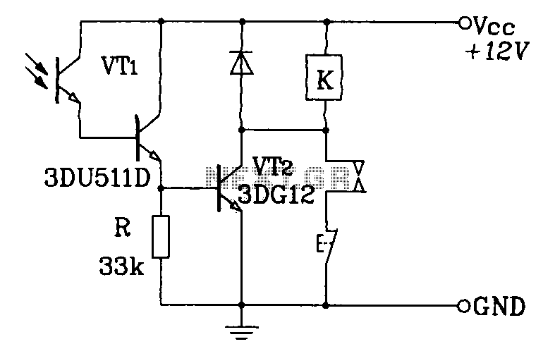
A Darlington phototransistor serves as the primary component for the photoelectric function within a self-locking control relay circuit. The circuit utilizes a Darlington phototransistor, which is known for its high current gain and sensitivity to light. This device is configured...
The circuit includes a momentary switch S1 that triggers an alarm pulse for the decade counter IC2, which increments its count with each alternating alarm pulse or the activation of switch S1. Ten variable resistors (VR1 through VR10) are...