
Sputnik QSO Party Transmitter Prototype

The transmitter prototype employs a Master-Oscillator Power-Amplifier (MOPA) configuration, utilizing vacuum tubes to generate RF signals. The Pierce oscillator, which is crystal-controlled, is responsible for producing the fundamental frequency, while the Class-C power amplifier is tasked with amplifying the RF signal for transmission. The design ensures that the PA stage operates only when driven by the oscillator, preventing potential damage or inefficiency that could arise from operating the PA without an input signal.
The circuit's performance is influenced by the careful selection and adjustment of components, particularly the feedback capacitor (C1), which is critical for ensuring stable oscillator operation and optimal loading for the crystal. The Pi-network serves as an impedance matching circuit, enhancing the efficiency of the power transfer to the antenna, while the low-pass filter is intended to suppress unwanted harmonic frequencies that may be generated during transmission.
The original keying strategy employed by Sputnik 1, which alternated between two frequencies, is an effective method for managing battery life and ensuring consistent operation. This approach allows for the transmitter to maintain a steady load on the power supply, which is particularly important in battery-operated devices. The proposed modifications, including the implementation of grid-block keying and the potential use of a low-pass filter, are essential considerations for improving the overall performance and reliability of the transmitter prototype.Here is my Sputnik QSO Party transmitter prototype. The RF output power is 450mW with 70Vdc @ 14. 4mA on the V2 anode. The V2 screen (G2) current is 1. 6mA. The V1 anode current is 1. 05mA with 45Vdc @ 176uA at the screen (G2). These little vacuum tubes arecapable performers, however, for long-life operation it`s important toheed the maximum electrod eratings as shown on the datasheets (links given below). The simple MOPA (Master-Oscillator -> Power-Amplifier) vacuum-tube radio transmitter circuit shown below was well-known in the mid-1950`s. A crystal-controlled Pierce oscillator drives a Class-C PA. The PA grid bias is derived from rectified PA grid current (thus; never run the PA stage without the oscillator drive signal present!).
The CW keying and transmit/receive switching circuitry are not shown in the circuit below. Please click here to listen to a strong-signal recording of the original Sputnik-1. The oscillator signal bleed-though during "key-up" intervals is clearly audible. This implies that the oscillator stage was allowed to run continuously. Presumably, only the power amplifier (PA) stage was keyed on/off. As such, I plan to only key my PA stage (via the anode supply or perhaps using grid-block keying). My oscillator will be switched off only while I`m receiving signals. A low-pass filter may be required between the Pi-network impedance matching circuit and the antenna. I have not yet checked the RF output spectrum, however the inherent Pi-network 2nd harmonic attenuation is only ~28dB. The value of C1 may have to be adjusted for your particular circuit layout. This capacitor helps both to maintain the optimum level of oscillator feedback and provide the proper loading capacitance for the quartz crystal resonator.
The drawing below shows the original Sputnik 1 keying plan for normal conditions; 0. 3 seconds on, 0. 3 seconds off. While the 40. 002MHz transmitter was off the 20. 005MHz transmitter was on, and vice versa. This helped to hold the battery load steady. 🔗 External reference
Related Circuits
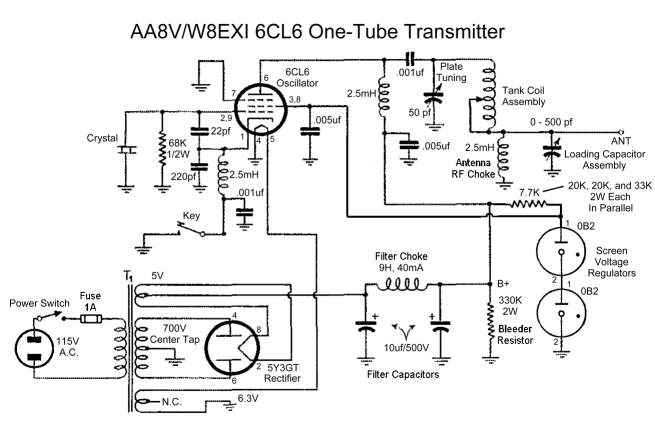
A8V W8EXI 6CL6 One Tube Transmitter. The operation of the 6CL6 transmitter is actually quite sophisticated. The A8V W8EXI 6CL6 One Tube Transmitter is a compact and efficient radio frequency (RF) transmitter that utilizes a single 6CL6 vacuum tube for...
This is an AM transmitter schematic diagram. The circuit is divided into two halves: an audio amplifier and an RF oscillator. The oscillator is constructed around Q1 and its associated components. The tank circuit, consisting of L1 and VC1,...
This circuit explains alternate wireless switching using an ultrasonic sensor. The distance of the switching range should be more than 10 meters. The described circuit employs an ultrasonic sensor to facilitate wireless switching, allowing for the activation or deactivation of...
The RF oscillator using the inverter N2 and 10.7MHz ceramic filter is driving the parallel combination of N4 to N6 through N3. Since these inverters are in parallel, the output impedance will be low so that it can directly...
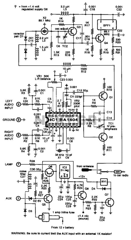
A BA1404 integrated circuit (IC) is utilized to generate a complete FM multiplex (MPX) signal. The chip incorporates all necessary circuitry. Components CI, R3, R4, and C4 are responsible for providing pre-emphasis. The transmitter operates on a single AA...
Here is a simple little HF TX. It may be modified for all the HF bands, but the details given are only for the 7MHz band. The basic transmitter uses two transistors; BC547 (as usual) and will deliver over...