
Twilight Lamp Blinker LDR project

The Twilight Lamp Blinker circuit operates by detecting ambient light levels through the LDR. As the light intensity decreases, the resistance of the LDR increases, triggering the IC to activate the lamp. This functionality is particularly useful in applications where automatic lighting is desired, such as in garden lamps or outdoor lighting systems.
The circuit typically consists of the following components:
1. **LDR (Light Dependent Resistor)**: This component changes its resistance based on the light intensity. In darkness, its resistance is high, while in light, it is low.
2. **Operational Amplifier (Op-Amp) or Comparator IC**: This IC compares the voltage across the LDR with a reference voltage. When the light level falls below a certain threshold, the output of the comparator changes state, allowing current to flow to the lamp.
3. **Transistor**: A transistor is often used as a switch to control the power to the lamp. When the IC output is activated, it turns on the transistor, which in turn powers the lamp.
4. **Resistors and Capacitors**: These components are used to set the reference voltage for the IC and to stabilize the circuit. Resistors limit current flow, while capacitors can help filter noise and stabilize voltage levels.
5. **Power Supply**: The circuit requires a suitable power supply, typically a battery or wall adapter, to provide the necessary voltage and current for the components.
The design can be adjusted for different applications by modifying the values of the resistors and capacitors or by selecting different types of lamps (e.g., LED or incandescent) based on the desired brightness and power consumption. The simplicity and effectiveness of the Twilight Lamp Blinker circuit make it a popular choice for automatic lighting solutions.Twilight Lamp Blinker circuit can be built with LDR and single IC circuit diagram with parts list of twilight lamp blinker various project using LDR and many more. 🔗 External reference
Related Circuits
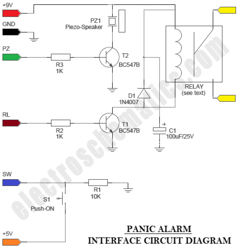
The circuit is an Arduino-based Panic Alarm. The wiring is straightforward, enabling even novices to construct this interesting circuit with ease. Arduino is a family of microcontrollers and a software environment (Arduino IDE) that facilitates the creation of programs,...
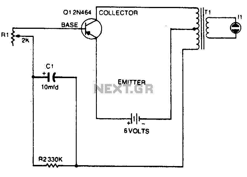
The universal output transformer and the transistor create a low-frequency oscillator. The flashing rate of the neon bulb is controlled by potentiometer R1. The circuit consists of a universal output transformer coupled with a transistor to form a low-frequency oscillator....
Building ESLs involves the use of tools and materials that if handled improperly can be hazardous. Please make sure you know how to use these things before you begin. By all means, use safety glasses at all times. If...
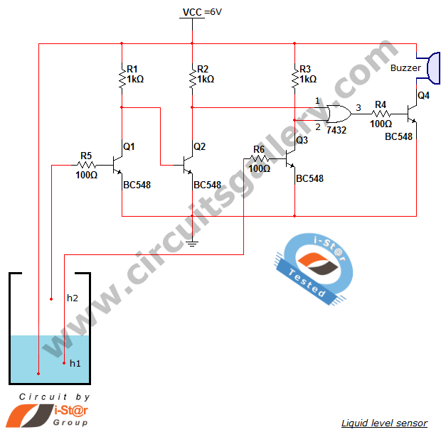
A variety of small electronic projects related to water level sensors have been posted in the Circuits Gallery. This particular project is designed for school students to detect the water level within a water tank or any other water...
The Implantable Lamp (A3024) is a radio-controlled lamp powered by a battery. Once encapsulated in epoxy and silicone, it is waterproof and compact, allowing it to be implanted in an animal. The A3024 can theoretically be activated by any...
The circuit provides sufficient illumination suitable for reading purposes. Capacitor CX, in conjunction with diodes D1 through D4, constitutes the AC step-down circuit. CX lowers the high voltage AC from the mains to a low voltage AC, which is...