
Neon blinker

The circuit consists of a universal output transformer coupled with a transistor to form a low-frequency oscillator. The primary function of this oscillator is to generate a periodic signal that can drive a load, in this case, a neon bulb. The neon bulb operates by ionizing the gas within it when a certain voltage threshold is reached, causing it to emit light.
The flashing rate of the neon bulb is adjustable and is determined by the resistance value set by potentiometer R1. This potentiometer allows for fine-tuning of the oscillator frequency by varying the resistance, which in turn affects the charging and discharging time of the capacitor in the circuit. As the resistance changes, it alters the time constant of the RC (resistor-capacitor) network, leading to a change in the frequency of the oscillation.
The output transformer serves to match the impedance of the oscillator circuit to the neon bulb, ensuring efficient energy transfer. The transistor acts as a switch that turns on and off at the oscillation frequency, controlling the current flowing through the transformer and ultimately the neon bulb.
This configuration is useful in applications where visual indication is required, such as in timers or alert systems, where the flashing of the neon bulb provides a clear visual signal. The adjustable flashing rate can be beneficial in various scenarios, allowing for customization based on specific operational requirements.The universal output transformer and the transistor form a low-frequency oscillator The rate of flashing of the neon bulb is determined by potentiometer Rl.
Related Circuits
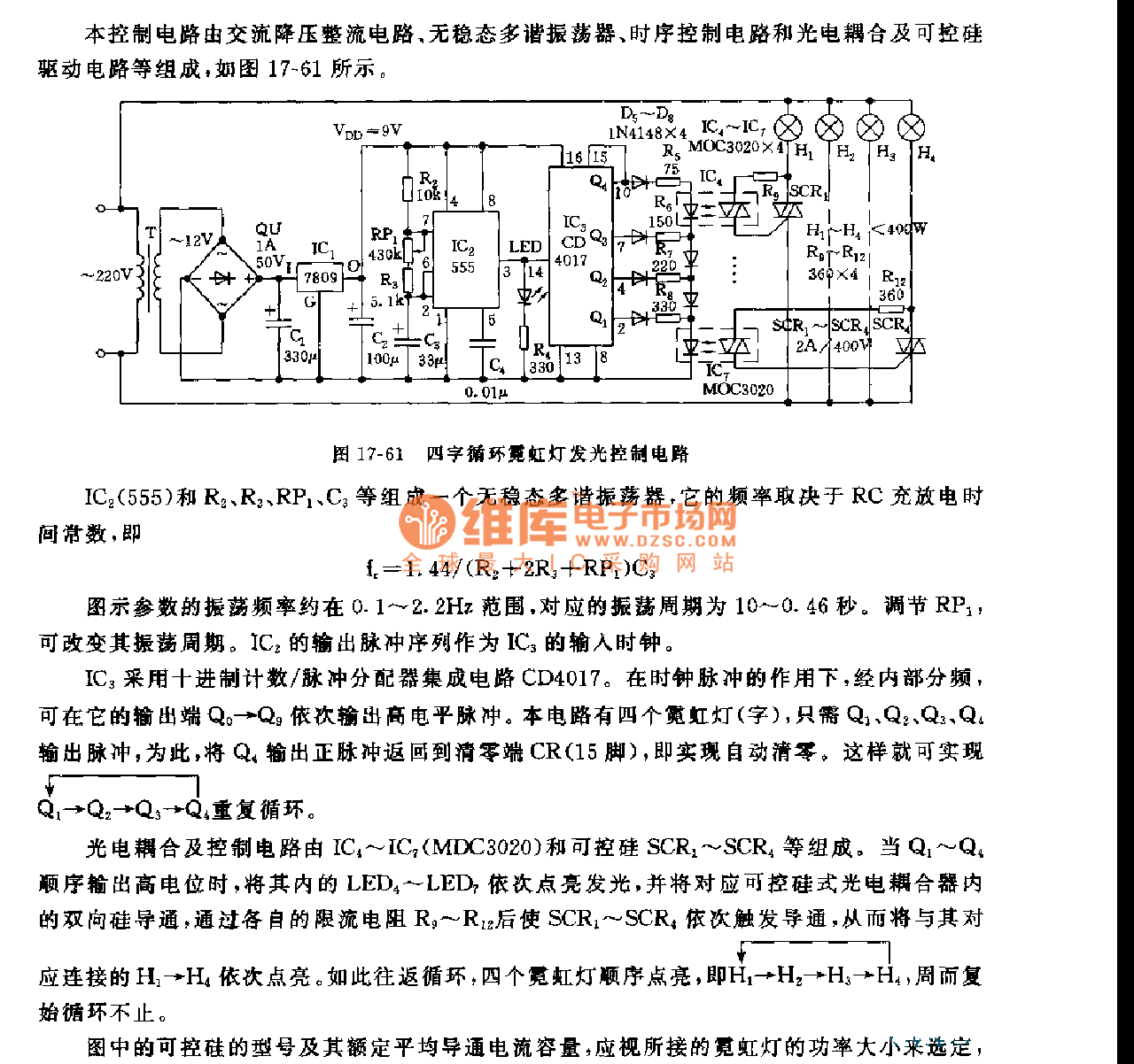
This control circuit consists of an AC step-down rectifier circuit, an astable multivibrator, a timing control circuit, an optocoupler circuit, and an SCR driving circuit, as illustrated in Figure 17-61. The astable multivibrator is formed using IC2 (555), resistors...
The circuit (before flameout) worked like this: device Q1 is a triac, which is a power-switching device. When triggered, it switches to a fully conducting state and stays that way until the current passing through it goes to zero....
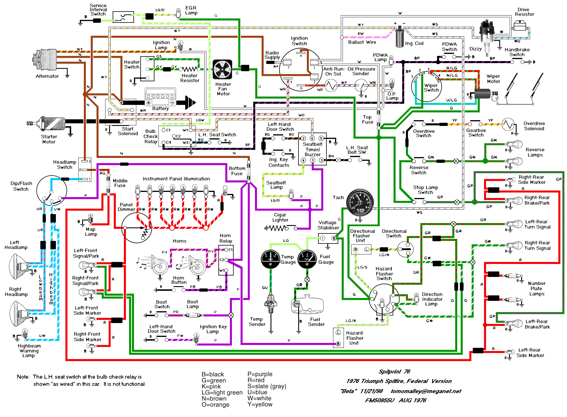
The Haynes manual is quite confusing regarding the labeling of relays on Spitfires. The two main sources of confusion are: 1. The illustrations depict right-hand drive cars with different relay locations, and 2. The naming of the relays is...
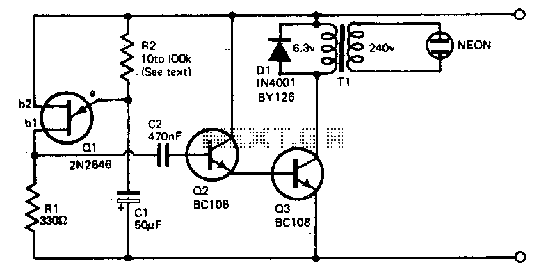
The voltage required to ignite the neon tube is generated by utilizing a standard filament transformer (240-6 V) in reverse. The battery drain is minimal, approximately 1 to 2 milliamps for a nine-volt battery. The pulses from Q1, a...
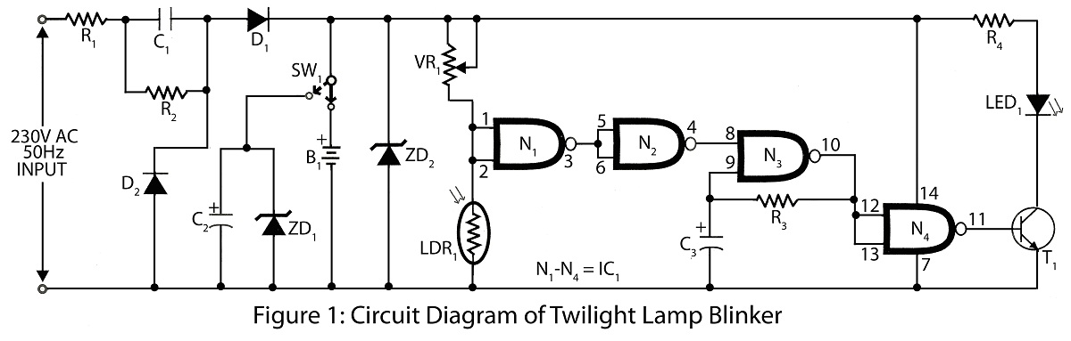
Twilight Lamp Blinker circuit can be constructed using a Light Dependent Resistor (LDR) and a single integrated circuit (IC). The circuit diagram includes a parts list for various projects utilizing the LDR and additional components. The Twilight Lamp Blinker circuit operates...

When the lamp turns off, a reset pulse is generated for the corresponding counter by NAND gate IC1. The counter then counts up again. The display's progression rate can be adjusted to the desired speed using potentiometer P1. Only...