
Twin-T Audio Sine Wave Oscillator

The circuit design is centered around the use of the TL072CP operational amplifier, which is favored for its low noise and high performance in audio applications. The twin-T network configuration is specifically chosen for its ability to produce a stable sine wave output, which is vital for testing audio equipment. The design emphasizes the importance of component selection; using resistors and capacitors with tight tolerances ensures that the oscillation frequency remains stable and accurate. The inclusion of the automatic gain control circuit enhances the usability of the oscillator by preventing amplitude fluctuations that could affect testing results. This design can be adapted for various applications by adjusting component values, allowing for flexibility in output frequency and amplitude. The circuit's low power consumption and ability to operate from a single battery make it suitable for portable applications, providing convenience without sacrificing performance. Overall, this sine wave oscillator circuit represents a robust solution for generating high-quality sine wave signals for audio testing and other applications.The circuit illustrated produces a clean sine wave signal ideal for audio testing, or wherever a good-quality sine voltage source is required. It uses one integrated circuit which is a widely-available dual operational amplifier, the Texas Instruments TL072CP.
The values shown provide an output frequency of about 1000 Hertz. This frequency may be varied over a wide range, using the equation shown in the schematic. Frequency is almost exclusively determined by the twin-T network in U1A`s feedback loop, provided that the gain-bandwidth product and slew rate specifications for the op amp are sufficiently high. For frequencies exceeding 10kHz, an faster op-amp in the U1A position is recommended. The oscillator`s frequency-selective twin-T network, C1, C2, C3, R1, R2, and R3, is in the negative feedback path of the operational amplifier.
U1A`s positive-input to output transfer function is a notch filter with a frequency and depth determined by those components` values, with zero degrees of phase shift at the notch frequency. The twin-T network characteristics are defined by these equations: The positive feedback required for oscillation is provided by R4.
Transistor Q1 is part of an automatic gain control (AGC) servo that regulates U1A`s positive feedback to keep the sine wave output at a consistent amplitude. The circuit will oscillate at the notch frequency when Q1`s emitter-to-collector resistance (Rec) is: U1B and its associated components complete the servo.
The series-connected diodes provide negative peak-level detection of the sine wave voltage and also determine the amplitude of the output. Q1 is operated close to maximum conduction, so the small voltage from its emitter to collector contributes negligible distortion to the sine wave.
The 0. 1uF integrating capacitor in U1B`s feedback path was chosen to provide adequate AGC-loop stability for the selected oscillation frequency. The 10K resistor in parallel with Q1 provides start-up. The ratios of the resistors and capacitors in the twin-T network must be accurate to ensure oscillation, and at the desired frequency.
For that reason, ±1% components are indicated. R1, R2, and R3 should be metal film, and C1, C2 and C3 should be C0G ceramic or mica (best), or polystyrene (good). Polyester capacitors may be used for economy if large C1, C2, and C3 values, such as those exceeding 10nF, are required.
A capacitor ratio of 2:1 is most conveniently obtained with the standard values that have that nominal relationship, e. g. , 750pF and 1500pF (as shown), 1000pF and 2000pF, 1100pF and 2200pF, 1500pF and 3000pF, and 1800 and 3600pF.
Alternatively, four equivalent capacitors may be used, with two of them paralleled to make C1. The same technique is also applicable for the three resistors, especially when an exact 2:1 ratio of resistance values is not available. Interestingly, Q1`s emitter and collector may be interchanged without any significant effect on the circuit`s performance, although convention dictates that the emitter is biased negatively with respect to the base.
If the two diodes are reversed, then Q1 may be a PNP transistor such as type 2N3906. The oscillator`s amplitude, as well as frequency, is essentially independent of the power supply voltage. An output amplitude of 1. 6 volts peak-to-peak was chosen to accommodate power supply voltages as low as 6 volts. Replacing the TL072CP with a rail-to-rail dual operational amplifier such as the Analog Devices type AD823AN will permit operation from even lower supply voltages, such as 4 volts.
The oscillator will operate conveniently from a single 9-volt battery, and consumes less than 5 milliamperes of current when using the TL072CP. The 470 ohm resistor in the output prevents instabilities from capacitive loads such as long cables, and the 1uF capacitor removes the DC offset at U1A.
The output`s 100K resistor discharges the 1uF capacitor to prevent voltage transien 🔗 External reference
Related Circuits

This design circuit is intended for sine wave oscillators, providing both sine and square wave outputs across a frequency range from below 20 Hz to above 20 KHz. The oscillation frequency can be easily adjusted by changing a single...
20W Bridge Audio Amplifier kit, based on the TDA2005 IC, a class B dual audio amplifier, specifically designed for car radio applications etc. More: Power supply - 18 VDC Output power - 20 W, 4 Ω IC built in Thermal Shut-down,...
I am attempting to construct a Hartley oscillator using a bypassed common emitter configuration. The goal is to achieve oscillation at a frequency of 200 kHz with a peak-to-peak voltage of 2 V, utilizing a BC547B transistor. The Hartley oscillator...
This circuit was designed for an audio amplifier project to control the speaker output relay. Its primary function is to manage the relay that activates the speaker output in the audio amplifier, ensuring a delay of approximately 5 seconds...
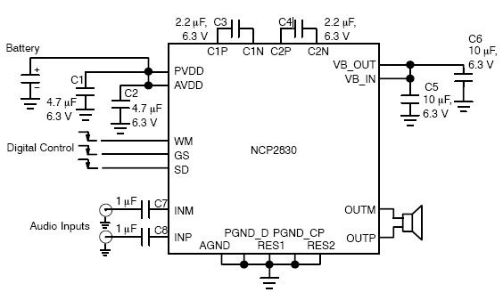
The NCP2830 audio power amplifier features high-quality audio performance with a total harmonic distortion plus noise (THD+N) of 0.04%. It offers low noise with a signal-to-noise ratio (SNR) of up to 100 dB and optimizes overall system efficiency, achieving...
Most cards of sound in computer are deprived stereo input for microphone; on the contrary, they have stereo input for high level (Line). The circuit uses the input Line of the sound card in order to connect two mono...