
Two HiJack Alarms

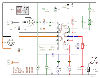
The described circuit functions as an anti-theft system specifically tailored for vehicles. The primary components include a door switch, an ignition switch, a timer, an alarm module, and an engine immobilizer relay.
When the vehicle ignition is active, the door switch is monitored. If the driver’s door is opened, the circuit is triggered, activating a timer. This timer is set to a predetermined delay, typically a few minutes, allowing the hijacker time to distance themselves from the vehicle. During this delay, the system remains in a standby mode, monitoring the status of the door switch.
Once the timer elapses, the alarm module is activated, emitting a loud sound to alert nearby individuals of the theft attempt. Simultaneously, the engine immobilizer relay is engaged, cutting off power to the vehicle's ignition system. This effectively disables the engine, preventing the hijacker from driving the vehicle further.
The design ensures that the system is sensitive enough to respond quickly to unauthorized access while providing a delay that minimizes false alarms due to accidental door openings. The use of a timer allows for a balance between security and practicality, making it an effective deterrent against vehicle theft.
In summary, this circuit is a robust solution that enhances vehicle security by integrating door monitoring, timed alarm activation, and engine immobilization to thwart potential theft attempts.The first circuit was designed for the situation where a hijacker forces the driver from the vehicle. If a door is opened while the ignition is switched on - the circuit will trip. After a few minutes delay - when the thief is at a safe distance - the alarm will sound and the engine will fail.
🔗 External reference
Related Circuits
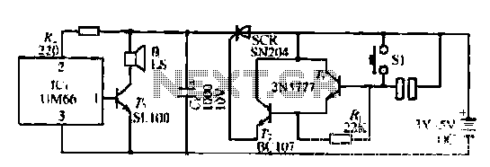
A few custom integrated circuits began to play music. When the song ends, no electricity flows through the thyristor, which then cuts off the light, causing the phototransistor to activate. The system is designed with a touchpad; each touch...
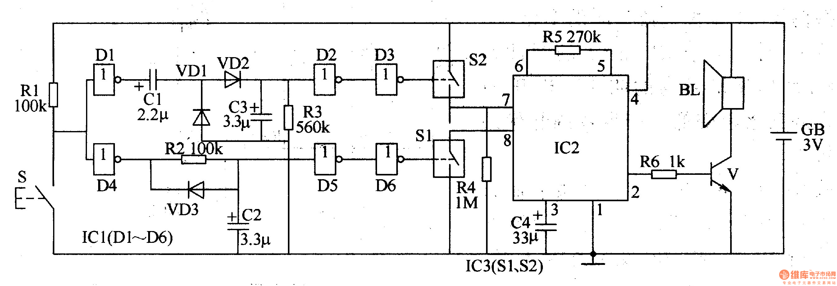
The two-tone electronic doorbell circuit comprises a trigger control circuit and a doorbell generating circuit, as illustrated in Figure 3-108. The trigger control circuit includes a doorbell button (S), resistors (R1-R3), electrical components (C1-C3), diodes (VD1-VD3), six NOT gate...
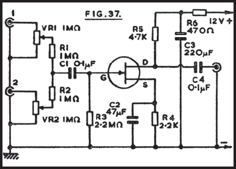
It is often convenient to fade in or out or mix the inputs from two audio sources at any desired level. The circuit depicted is suitable for this purpose. One input connects to socket 1, and the second to...
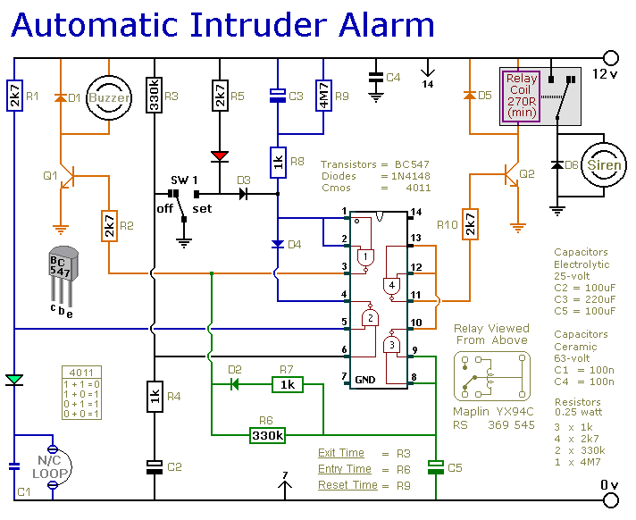
This is a simple single-zone home alarm system circuit. Its features include entry delays, a timed siren cut-off, and automatic exit. It is designed to be used with the usual types of normally-closed input devices such as foil tape,...
This is a two-zone alarm system featuring automatic exit, entry, and siren cut-off timers. It can be activated by standard normally-closed input devices, such as magnetic reed contacts, foil tape, and passive infrared sensors (PIRs). The circuit operates on...
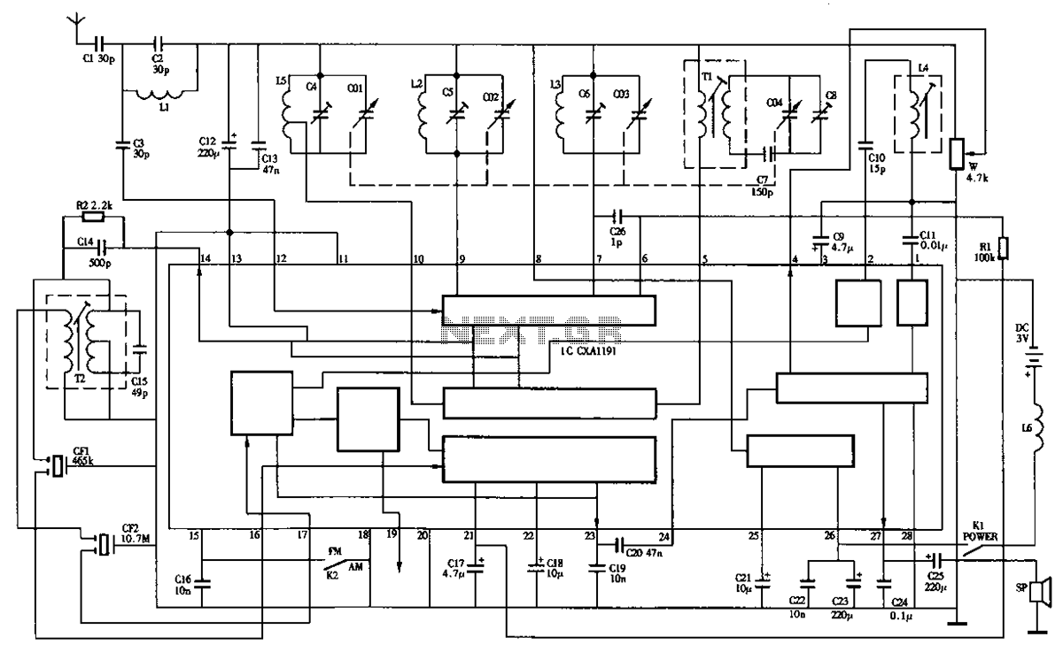
The circuit diagram of the Desheng R-202T type two-band radio is as follows. The Desheng R-202T is a two-band radio receiver designed to operate on both AM and FM frequencies. The circuit typically includes several key components that facilitate the...