
Two-tone electronic doorbell 2

The two-tone electronic doorbell circuit is designed to produce two distinct tones when activated. The trigger control circuit initiates the operation upon pressing the doorbell button (S). This button is connected to a series of resistors (R1-R3) that help manage the current flow and protect the circuit from excessive voltage. The capacitors (C1-C3) serve to filter and stabilize the voltage, ensuring a consistent operation.
Diodes (VD1-VD3) are included in the circuit to prevent reverse polarity and protect sensitive components from potential damage. The six NOT gate integrated circuits (IC1, D1-D6) are configured to generate the two-tone sound by manipulating the input signals from the trigger control circuit. These gates provide the necessary logic to switch between the two tones based on the state of the doorbell button.
The electronic switch (IC3, S1, S2) acts as a relay that connects the doorbell generating circuit to the power supply. When the button is pressed, the trigger control circuit activates the electronic switch, allowing current to flow to the doorbell generating circuit, which produces the audible tones.
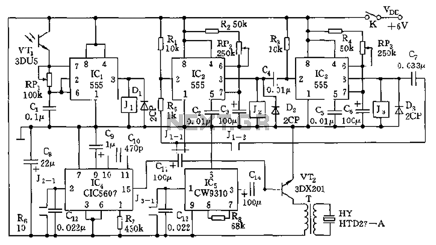
Overall, this circuit design effectively combines various electronic components to create a functional and reliable two-tone doorbell system. The integration of logic gates and protective elements ensures durability and performance, making it suitable for residential or commercial applications.The two-tone electronic doorbell circuit is composed of the trigger control circuit and doorbell generating circuit, and it is shown in Figure 3-108. Trigger control circuit consists of doorbell button S, resistors Rl-R3, electrical wear devices Cl-C3, diodes VDl-VD3, six NOT gate integrated circuit ICl (Dl-D6) and the electronic switch IC lC3 (S1, S2).
Door.. 🔗 External reference
Related Circuits
AM radio receivers demodulate amplitude-modulated (AM) signals. The primary source of these signals is the Standard AM Radio Broadcast Band, although shortwave stations also utilize AM modulation. Amplitude modulation was developed between 1900 and 1917 by amateur radio enthusiasts....
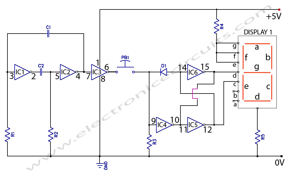
Electronic Coin Toss Circuit Diagram. This is an electronic coin toss circuit using one CD4049 IC (Hex inverting buffer and TTL driver). The electronic coin toss circuit utilizes the CD4049 integrated circuit, which serves as a hex inverting buffer...
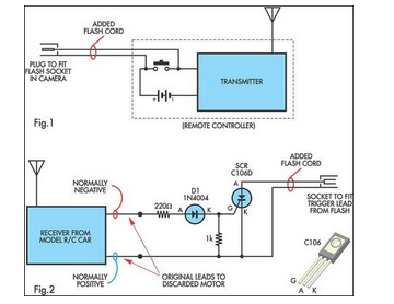
A radio-controlled electronic flash is an essential tool in any photographer's kit. Professionals frequently utilize them, such as wedding photographers. A radio-controlled electronic flash system typically consists of a transmitter and one or more receivers. The transmitter, often mounted on the...
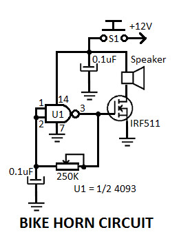
This simple electronic bicycle horn circuit utilizes a single gate from a 4093 quad 2-input NAND Schmitt trigger (U1) connected in a straightforward, low-frequency square wave configuration. The electronic bicycle horn circuit operates by generating a square wave signal that...
The circuit consists of four light-controlled electronic switches, timing circuits, voice circuits, audio circuits, and other components. It is designed to celebrate birthdays or similar occasions, with features such as birthday candles that can be lit or extinguished. The...
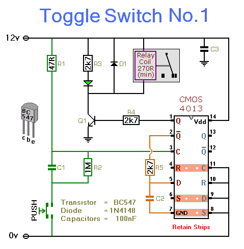
This circuit activates and deactivates a relay with the press of a button. Any momentary push-to-make switch can be utilized. Pressing the button once will activate the relay, while pressing it again will deactivate the relay. The circuit is...