
Two-phase stepper motor drive system circuit

The two-phase stepper motor control system utilizing the UC3717A is designed to provide precise positioning and speed control for applications requiring accurate motion. The UC3717A is a versatile integrated circuit that facilitates the generation of control signals necessary for the operation of stepper motors. By employing two of these ICs, the system can effectively manage the stepper motor's phases, allowing for smooth and reliable operation.
The microcomputer interface can be programmed to execute various control algorithms, which can be tailored to the specific requirements of the application. This flexibility enables the implementation of different operational modes, such as full-step, half-step, or microstepping, enhancing the motor's performance and resolution.
CMOS digital circuits are employed to generate the control signals, ensuring low power consumption and high-speed operation. The design can incorporate additional features such as speed control, direction control, and acceleration profiles, which can be programmed into the microcomputer. This adaptability makes the system suitable for a wide range of applications, from robotics to CNC machinery.
In summary, the combination of UC3717A components and microcomputer control provides an effective solution for managing two-phase stepper motors, allowing for precise control and versatility in various operational modes.Two-phase stepper motor typical application is shown in Figure 5-15 Xin, made up of two pieces UC3717A can form a two-phase permanent magnet or hybrid stepping motor microcomputer control system. By the microcomputer software design or by the TTI. , CMOS digital circuits can generate the correct hardware I ,, 1. , PHASE two-phase control signal, operation of several control modes.
Related Circuits
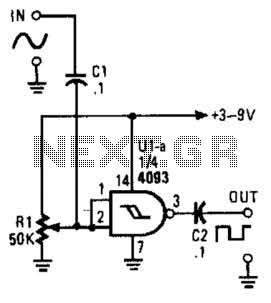
This circuit converts a sine wave into a square wave. It consists of a single 2-input NAND Schmitt trigger configured as an inverter, with an adjustable trigger level at its input. As the input voltage exceeds the gate's trigger...
This is a game timer circuit diagram. When the game timer is reset, two actions must occur: the 4017 counter must return to zero, and the 4060... The game timer circuit utilizes the 4017 decade counter and the 4060 binary...
This application note outlines the development and implementation of a Digital Weigh-Scale (DWS) utilizing Zilog's Z8 Encore! Microcontroller. The reference design provides a ready-to-use DWS solution that is easily scalable for measuring high-capacity loads. An external high-resolution Analog-to-Digital Converter...
This timer was designed primarily to turn off a portable radio after a specific duration. This feature allows users to fall asleep on the beach or in a hammock, with the assurance that the radio will automatically shut off...
This circuit is designed to signal the exceeding of a fixed threshold in room noise through a flashing LED. Three fixed levels are selectable: 50, 70, and 85 dB. Two operational amplifiers provide the necessary gain for sounds captured...
The color wheel and motor control are customizable. This system utilizes field-sequential color rather than the "compatible color" introduced later. Following the wiring modifications, further details about the color wheel will be provided. Without the wheel, CBS shows can...