
Two Simple Thermistor-Controlled Relay Circuits

The thermistor plays a crucial role in this setup. When the temperature is high, the relay should be energized, requiring pins 5 and 6 to be low. Conversely, when the temperature is low, the relay should be de-energized, necessitating that pins 5 and 6 be high. A CMOS input pin is considered high when it exceeds half the supply voltage and low when it falls below this threshold. In this circuit, a 12-volt supply is used, meaning that for high temperatures, pins 5 and 6 must be below 6 volts, and for low temperatures, they must be above 6 volts. The voltage on pins 5 and 6 can be controlled using a potential divider, which consists of resistors connected in series. The voltage drop across each resistor is proportional to its resistance value. For instance, connecting two 10k resistors in series across the supply will yield a 6-volt drop across each, effectively dividing the 12-volt supply into two equal portions. However, resistors of different values can also be used, with the voltage across each resistor depending on its resistance. In this circuit, R1 and the thermistor form a potential divider, with R2 playing a minor role that can be disregarded for the moment. The voltage across the thermistor is critical for determining the state of pins 5 and 6 based on temperature variations.You can use a Cmos 4001 or a Cmos 4011 in this circuit. They have four - two-input - gates. In each case - the two inputs are joined together. So the gates are being used as simple inverters. = This means that when the two inputs are high - the output will be low. And when the two inputs are low - the output will be high. = The output from the cir cuit is at pin 10. When pin 10 goes low - it`s connected internally to the negative line. So it connects the base of Q1 to ground - through R3. This allows base current to flow through the transistor`s emitter-base junction. And R3 limits the size of that current - to about 5mA. = When current flows through the emitter-base junction of Q1 - it switches the transistor on. The transistor connects the negative side of the relay coil to ground - and the relay energizes. = When pin 10 goes high again - it`s connected internally to the positive line. So it connects the base of Q1 to the positive line - through R3. This cuts off the base current`s path to ground. = Without its base current - the transistor switches off. This disconnects the negative side of the relay coil from ground - and the relay de-energizes. = In other words - every time pin 10 goes low - the relay will energize. And every time pin 10 goes high - the relay will de- energize. Thus - the state of the relay is controlled by the state of pin 10. = The state of pin 10 is controlled by the voltage on pins 5 & 6. = The gates are being used as simple inverters. So - if pins 5 & 6 are high - pin 4 will be low. Pin 4 takes pins 1 & 2 low - so pin 3 will be high. Pin 3 takes pins 12 & 13 high - so pin 11 is low. Pin 11 takes pins 8 & 9 low - so pin 10 is high. = In other words - while pins 5 & 6 remain high - the relay will remain de-energized. The opposite is also true. = If pins 5 & 6 are low - pin 4 will be high. Pin 4 takes pins 1 & 2 high - so pin 3 will be low. Pin 3 takes pins 12 & 13 low - so pin 11 is high. Pin 11 takes pins 8 & 9 high - so pin 10 is low. = In other words - while pins 5 & 6 remain low - the relay will remain energized. = THE ROLE OF THE THERMISTOR = When the temperature is high - we want the relay to be energized. So we want pins 5 & 6 to be low. And when the temperature is low - we want the relay to be de-energized. So we want pins 5 & 6 to be high = A cmos input pin is high - when it`s over half the supply voltage. And a cmos input pin is low - when it`s below half the supply voltage. I`ve used a 12-volt supply in the diagram. This means that - while the temperature is high - we need pins 5 & 6 to be below 6-volts. And - while the temperature is low - we need pins 5 & 6 to be above 6-volts. = We can control the voltage on pins 5 & 6 with a potential divider. A potential divider is no more than a number of resistors connected in series. A portion of the supply voltage appears across each resistor. And the size of that portion depends on the value of the resistor concerned. = For example - if we connect two 10k resistors in series across our supply - there will be a drop of 6v across each one.
In other words - the 12-volt supply potential will be divided into two equal portions - of 6-volts each. = But the resistors don`t have to be the same value. When resistors with different values are connected in series - the voltage across each resistor - is in proportion to its value.
For example - if you connect a 10k resistor and a 15k resistor in series across the supply - two-fifths of the 12v will appear across the 10k resistor - and the remaining three-fifths will be across the 15k resistor. In other words - there`ll be 4v8 across the 10k resistor - and 7v2 across the 15k resistor. = Back to pins 5 & 6 and the thermistor. R1 & R2 form a potential divider with the thermistor. R2 only plays a minor role - and you can ignore it for the present. So our potential divider is made up of R1 and the thermistor. And the voltage across the thermistor determ 🔗 External reference
Related Circuits
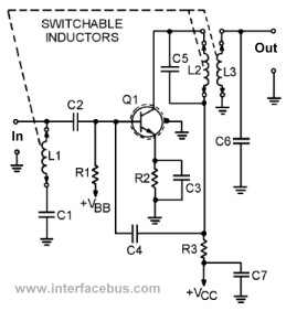
This page presents several transistor circuits that are not commonly found on other pages due to the absence of a specific topic. These circuits, however, illustrate particular points but lack detailed descriptions. An example of an RF amplifier circuit...
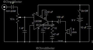
This is a simple low-power audio amplifier circuit capable of producing a power output of 1W. The mono amplifier circuit is built around the LM386 integrated circuit, which operates effectively at low voltages, even below 9V. This low-voltage amplifier...
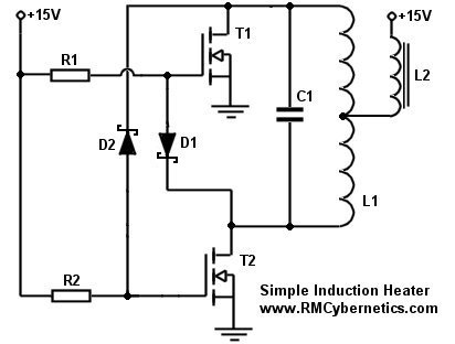
This project outlines the process of creating a simple induction heater. It is straightforward and notably efficient at heating metals through the use of high-frequency magnetic fields. An induction heater operates on the principle of electromagnetic induction, where an alternating...

This design circuit is a tone control circuit that utilizes the popular Baxandall configuration, a straightforward circuit layout that allows for continuous boost and cut control. The circuit is inexpensive to construct and is frequently implemented in commercial products....
This circuit provides a straightforward method for measuring the voltage of a low-impedance voltage source. It operates as follows: P1, a 1-W potentiometer, acts as a voltage divider in conjunction with resistor R1. The voltage at their junction is...
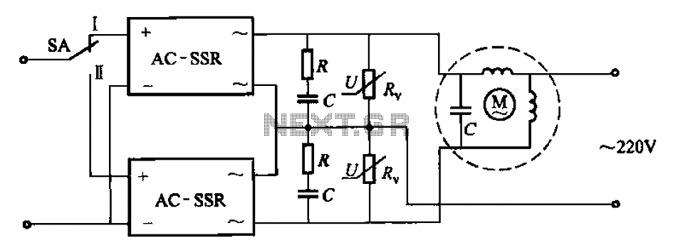
The circuit illustrated in Figure 3-14 features a SA switch positioned in the work state, allowing for motor operation. When the SA switch is set to the reverse position, the motor's direction is inverted. Additionally, an over-voltage protection element...