
555 direct reading frequency meter schematic

The frequency meter circuit is designed to provide accurate frequency readings through a combination of amplification and signal conditioning. The initial amplification stage, utilizing LM741 operational amplifiers, enhances the weak input signals typically encountered in frequency measurement applications. The use of two amplifiers allows for a cascading gain effect, which ensures sufficient signal strength for the subsequent processing stages.
Following amplification, the Schmitt trigger stage plays a crucial role in signal shaping. It converts the amplified analog signal into a clean digital signal, which is essential for accurate frequency measurement. The Schmitt trigger's hysteresis characteristics ensure that the output remains stable and free from noise, regardless of variations in the input signal amplitude.
The monostable trigger circuit, implemented with the 555 timer, introduces a time-dependent response to the frequency of the input signal. By adjusting the resistors (R12 to R15) and capacitor (C5), the user can modify the timing characteristics of the monostable output. This flexibility allows the circuit to adapt to a range of input frequencies, making it suitable for various applications.
The output of the 555 timer is directly related to the frequency of the input signal, which influences the deflection angle of the measuring table pointer. This relationship provides a visual representation of the frequency, making it easier for users to interpret the readings.
In addition, the inclusion of a DW regulator ensures that the pulse amplitude remains consistent, which is critical for maintaining the accuracy of the frequency readings. The ability to adjust the reference voltage using RP1 allows for precise calibration of the frequency meter, ensuring that it delivers reliable and accurate measurements across its operational range. Overall, this frequency meter circuit is a versatile and effective tool for frequency measurement in various electronic applications.Direct reading frequency meter by the amplifier, and trigger one-shot circuit and table top components. It can be directly detected in the read head of the table 1mA signal, th e maximum signal frequency up to 20kHz, sensitivity is not less than 100mV. IC1, IC2 using LM741 operational amplifier is used as a first amplifying stage, the second stage is a Schmitt trigger, the input signal is shaped so that the frequency of IC2 output signal frequency of the input signal is the same. Independent of the input signal amplitude. 555 and R12 ~ R15, C5 etc. monostable trigger circuit, monostable duration of temporary stability in accordance with the level of the input signal frequency, choose a different time constants, or file, 555 output high duration proportional to the frequency of the input signal, thereby changing table pointer deflection angle.
DW regulator use as a chopper, so added to the header of the same pulse amplitude. 555 can be varied to adjust RP1 internal comparator reference voltage value, that is the time to change the monostable continued to the present frequency meter calibration.
Related Circuits

This design circuit is for a digital voltmeter. The integrated circuit ICL7107 serves as a 3-1/2 digit LED analog-to-digital converter (A/D converter). It includes an internal voltage reference, high isolation analog switches, sequential control logic, and display drivers. An...
The use of diode rectifiers in AC voltmeters with a low lower limit of measurement range (0.5-1 V) leads to significant nonlinearity of the scale due to the nonlinearity of the current-voltage characteristics of diodes. The incorporation of electronic...
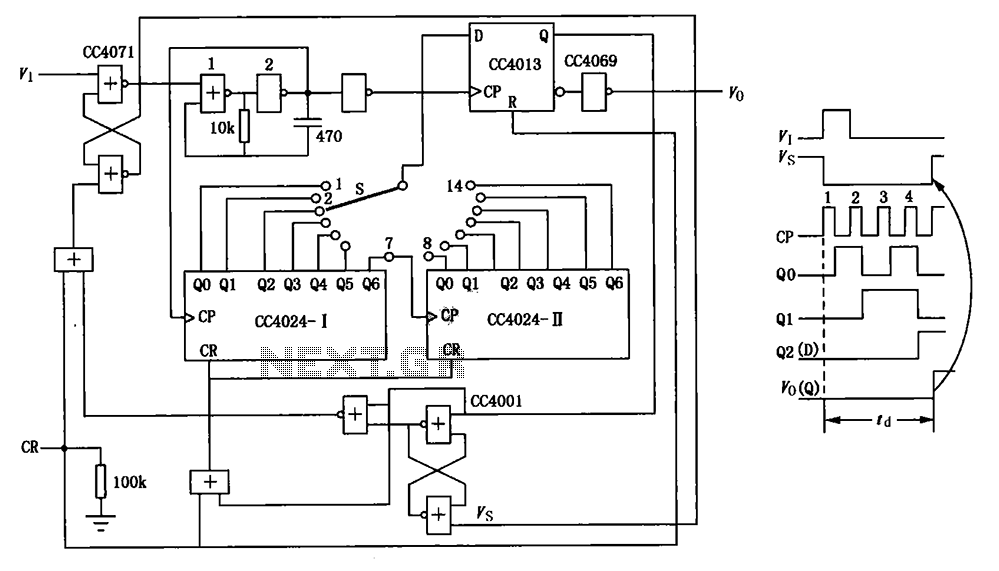
The circuit depicted in the figure is an optional delay circuit with a division factor. It consists of two 7-bit binary serial counters (CC4024) along with a controlled pulse source, which is composed of gate 1 and gate 2,...
Pin 3 defines the Display type: Common Cathode or Common Anode. Connect this pin to GROUND if you are using common cathode 7-segment led displays. To use common anode displays, connect it to VCC (positive). Pin 4 is the...
This circuit allows for the measurement of the actual output power of an amplifier. It can be housed in a box to function as a measurement instrument. The circuit for measuring amplifier output power typically includes a few essential components:...
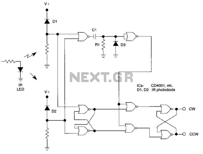
The circuit utilizes two CD4001 packages, incorporating eight NOR gates. It operates by receiving pulse streams that are input to an RS flip-flop, producing an output waveform with a variable duty cycle based on the direction of rotation. The...