
H-Bridge Motor Driver using MOSFETs and Transistors

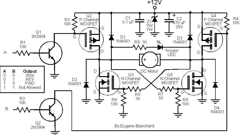
The H-Bridge Motor Driver circuit is an essential component in various applications, including robotics and automation, where bidirectional control of a motor is required. The circuit consists of four switching elements, typically MOSFETs or transistors, arranged in an 'H' formation. These switches control the flow of current through the motor, allowing it to rotate in either clockwise or counterclockwise directions.
In operation, the H-Bridge can be controlled by applying signals to the gates of the MOSFETs. For instance, turning on switches S1 and S4 allows current to flow through the motor in one direction, while activating switches S2 and S3 reverses the current flow, thus reversing the motor's direction. This capability is crucial for applications that require precise control over motor movement.
Additionally, when all switches are turned off, the motor is effectively disconnected from the power source, allowing it to coast to a stop. This feature is beneficial for energy efficiency and helps to prevent unnecessary power consumption when the motor is not in use.
In a typical implementation, the control signals for the MOSFETs can be provided by a microcontroller or a dedicated motor driver IC. The choice of MOSFETs should be based on the motor's voltage and current ratings to ensure reliable operation. Proper heat dissipation mechanisms, such as heat sinks, may also be necessary to manage thermal performance during operation.
The comprehensive understanding of the H-Bridge circuit's operation, along with its configuration and control mechanisms, is vital for engineers and designers working with motor control applications.In this post, we shall be covering on how to construct a H-Bridge Motor Driver circuit using simple MOSFET`s and Transistors. The main feature of this H-Bridge is that the motor can be driven in both directions. AnH-bridgeis a circuitthat allows a voltage to be applied across any load, like a motor in our experiment, in dual directions.
The `H` h ere just represents the formation of the circuit and has no reference to anyone. The H-bridge arrangement is generally used to reverse the polarity of the motor and to let the motor `free run` to a stop, as the motor is effectively disconnected from the circuit. The following table summarizes operation, with S1-S4 corresponding to the diagram above. 🔗 External reference
Related Circuits
This circuit is designed for children's entertainment and can be installed on bicycles, battery-powered cars, motorcycles, as well as on models and various games and toys. When switch SW1 is positioned as depicted in the circuit diagram, it generates...
These circuits could be used as the basis for Model Railroad DCC Boosters or PWM motor controllers. The first schematic is for a basic 3 Amp - DCC Booster using the LMD 18200 CMOS, H-Bridge. Included in the design...
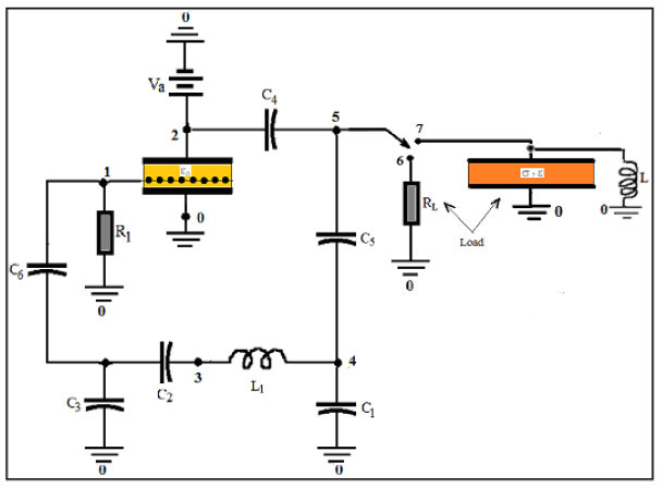
COMSOL's integration of SPICE® elements into its finite element method (FEM) allows for direct modeling of oscillators. In this approach, the triode and load are described using FEM, while all other circuit components are simulated with SPICE®. This modeling...
This project measures the clock pulses supplied to the Timer input of the AVR microcontroller. The Bascom code counts the clock pulses over a duration of 1 second and displays the result. The circuit for this project primarily consists of...
At 9 volts, the maximum stalled current of the motor types intended for use will be 700 mA. The selection of appropriate MOSFETs is crucial, particularly regarding their ratings for current and voltage handling. However, there are concerns about...
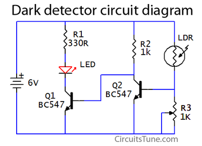
This is a basic dark detector or sensor circuit diagram based on a photoresistor (LDR) and a few components. The dark detector circuit utilizes a photoresistor (LDR) as the primary sensing element. The LDR is a light-dependent resistor that changes...