
Two-speed motor stator winding 2Y-Y connection

The two-speed motor stator wiring diagram depicted in Figure 3-100 provides a clear representation of the electrical connections required for the operation of a two-speed induction motor. The 2Y/Y connection indicates that the motor windings are connected in a wye configuration, which is essential for enabling the motor to operate at two different speeds.
In this configuration, the stator windings are divided into two sets, allowing for the selection of different voltage levels depending on the desired speed. The diagram typically includes labels for each winding, as well as the corresponding lead connections that facilitate the switching between high and low-speed operations.
The 2Y/Y connection is advantageous because it allows for reduced starting currents and improved efficiency during operation. The diagram may also illustrate the use of contactors or relays that are employed to switch between the two speed settings. Proper understanding and implementation of this wiring diagram are crucial for ensuring the motor operates effectively and reliably in its intended application.
In summary, Figure 3-100 serves as a vital reference for engineers and technicians involved in the installation, maintenance, and troubleshooting of two-speed motors, providing essential information on the connections and configurations necessary for optimal performance.Fig. 3-100 is a two-speed motor stator windings lead wiring diagram 2Y/Y-connected.
Related Circuits
The following circuit illustrates the circuit diagram of a motor control unit. This circuit is based on the LM317 integrated circuit (IC). Features include diodes that protect the regulator. The motor control unit circuit utilizes the LM317 voltage regulator to...
The individual has been engaged in garden railroading for just over a year, utilizing skills from various hobbies. They have designed and built two scratch-built bridges and nearly 100 trestle bents to support a 200-foot main line. Their interests...
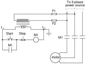
The most challenging aspect of interpreting ladder diagrams, particularly for individuals familiar with electronic schematic diagrams, is the representation of electromechanical relays. The operation of a motor control circuit should be explained, detailing what occurs when the "Run" switch...
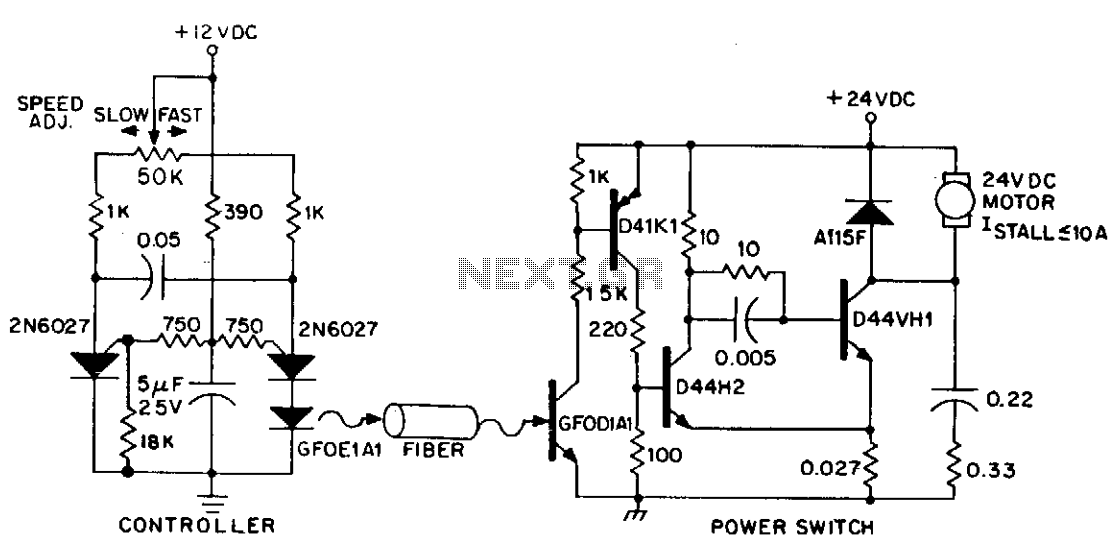
DC power can also be controlled using fiber optics. The circuit provides an insulated speed control path for a small DC actuator motor (less than Vn hp). The control logic is a self-contained module that requires approximately 300 mW...
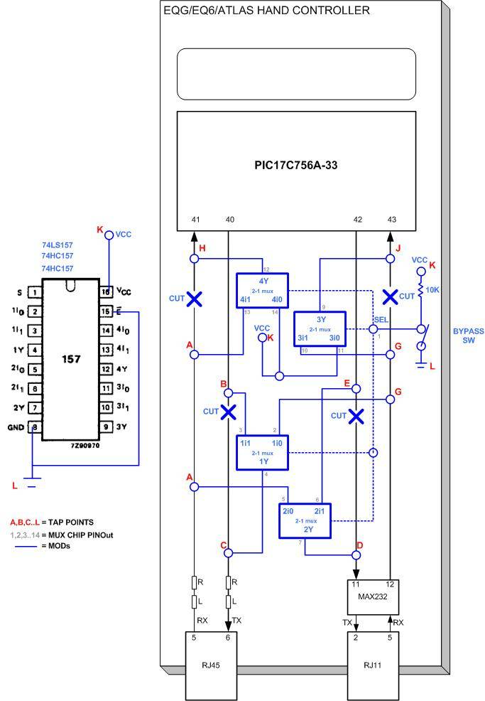
The modifications allow direct access to the stepper motor controls of the mount. Any erroneous commands or invalid data sent to the mount could inadvertently activate the stepper motors, leading to potential damage to connected equipment as the motors...
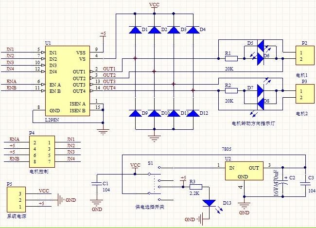
1. Driver: L298N Dual H Bridge DC Motor Driver IC 2. Supply voltage for the driven part (Vs): +5 V to +35 V; for internal board power supply, Vs: +7 V to +35 V 3. Peak current for the...