
DC variable speed motor control

The average supply voltage to the motor is pulse-width modulated to achieve the desired speed, while the current is maintained between pulses by the A115F freewheeling diode. A snubber network connected in parallel with the power switch minimizes peak power dissipation in the output transistor, thereby enhancing reliability. For larger horsepower motors, an additional stage of current gain can be added, and longer fiber optic range lengths can be achieved by utilizing an amplifier transistor to drive the GFOE1A1.
This circuit employs fiber optics for the transmission of control signals, ensuring electrical isolation between the control module and the motor. The use of infrared pulses facilitates reliable communication over distances without the need for conductive materials, which can be beneficial in environments where electromagnetic interference is a concern. The Schmitt trigger configuration enhances the stability of the switching process, reducing the likelihood of false triggering due to noise.
The programmable unijunction multivibrator serves as a pulse generator, allowing for precise control of the motor speed through the adjustment of the potentiometer. This flexibility enables the user to fine-tune the motor's performance according to specific application requirements. The D39C1 PNP Darlington transistor amplifies the signal from the infrared detector, ensuring that sufficient current is available to drive the power switch effectively.
Overall, this circuit design showcases an efficient method of controlling small DC motors using fiber optics, combining the benefits of electrical isolation, precise speed control, and enhanced reliability through careful component selection and configuration.Dc power can also be controlled via fiberoptics. The circuit provides an insulated speed control path for a small dc actuator motor (< Vn hp). Control logic is a self-contained module requiring about 300 mW at 12 V, which can be battery powered. The control module furnishes infrared pulses, at a rate of 160 Hz, with a duty cycle determined by the position of the speed adjust potentiometer.
The programmable unijunction multivibrator provides approximately 10 mA pulses to the GFOE1A1 at duty cycles adjustable over a range of 1% to 99%. Hie infrared pulses are detected by the GFOD1A1, amplified by the D39C1 pnp Darlington, and supplied to the power drive switch, which is connected in a Schmitt trigger configuration to supply the motor voltage pulses during the infrared pulses.
Thus, the motor's average supply voltage is pulse width modulated to the desired speed, while its current is maintained between pulses by the A115F freewheeling diode. The snubber network connected in parallel with the power switch minimizes peak power dissipation in the output transistor, and enhancing reliability.
Larger hp motors can be driven by adding another stage of current gain, while longer fiber range lengths can be obtained with an amplifier transistor driving the GFOE1A1.
Related Circuits
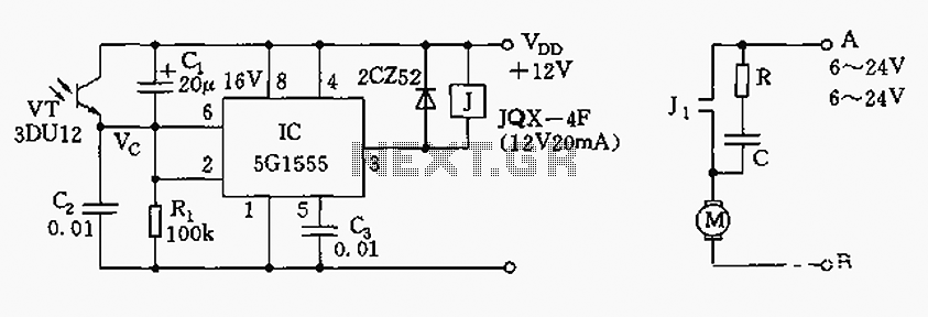
The control circuit consists of an NE555 timer and a phototransistor, along with resistors R1, capacitors C1 and C2, among other components. The photodiodes 3DU12 respond to sunlight by decreasing their resistance, which causes the voltage at the 555...

This keypad is designed for use with the Modular Burglar Alarm system, although it can be applied in various other contexts. Inputting the first four digits of a selected five-digit code will activate the relay, while entering the complete...

Figure 3173 illustrates a control circuit for a wound rotor induction motor that enables mechanical braking, dynamic braking, and reverse braking functions. The circuit includes various components such as relays, contactors, and time relays to manage the motor's speed...
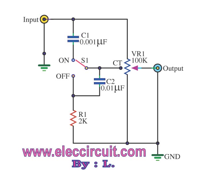
The passive tone control circuit is designed to adjust the bass without expansion, utilizing resistors (R) and capacitors (C). It functions as a frequency filter and is easy to construct, requiring no external power supply. This circuit can be...
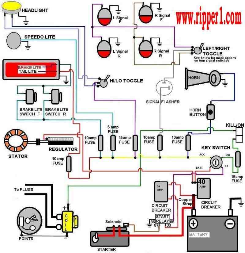
Customs by Ripper - A technical page focused on basic wiring for any vehicle, particularly motorcycles. The page serves as a valuable resource for individuals seeking to understand the fundamentals of vehicle wiring, with a specific emphasis on motorcycles....
This is a very useful project for anyone working in electronics. It is a versatile power supply that will solve most of the supply problems arising in the everyday work of any electronics workshop. It covers a wide range...