
Siemens S566B Electronic Touch Dimmer

The circuit utilizes the S566B IC, which is specifically designed for touch-sensitive applications, to enable a dimming function for a lamp. The S566B operates by detecting touch input, allowing users to control the brightness of the lamp by simply tapping on the designated area.
In this application, the S566B is connected to a power supply that provides the necessary voltage and current for the lamp. The output of the S566B is connected to a triac, which acts as a switch to control the power delivered to the lamp. When the touch sensor detects a touch, the S566B sends a signal to the triac, which then adjusts the current flowing to the lamp, effectively dimming or brightening the light output.
The circuit may also include additional components such as resistors and capacitors to filter noise and stabilize the operation of the S566B. A diode may be used for protection against reverse polarity, ensuring the longevity and reliability of the circuit.
Overall, the design provides a user-friendly interface for adjusting lamp brightness, making it suitable for various applications where adjustable lighting is desired. The touch dimmer functionality enhances convenience and modernizes the traditional lamp design.The circuit was designed to create a lamp that incorporates the operation of a touch dimmer using S566B integrated circuit manufactured by Siemens. S566B.. 🔗 External reference
Related Circuits
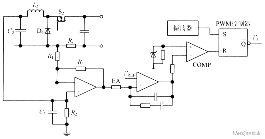
The circuit is capable of enhancing the system power factor to a value exceeding 0.99. It effectively reduces the waveform distortion of the input supply current, ensuring compliance with GB15144 standards, with a distortion index lower than level L....

A simple 16-volt switching power supply circuit can be constructed using the provided diagram, which is based on the MAX668 constant-frequency, pulse-width modulating (PWM), current-mode DC-DC controller. This integrated circuit is designed for a wide range of DC-DC conversion...
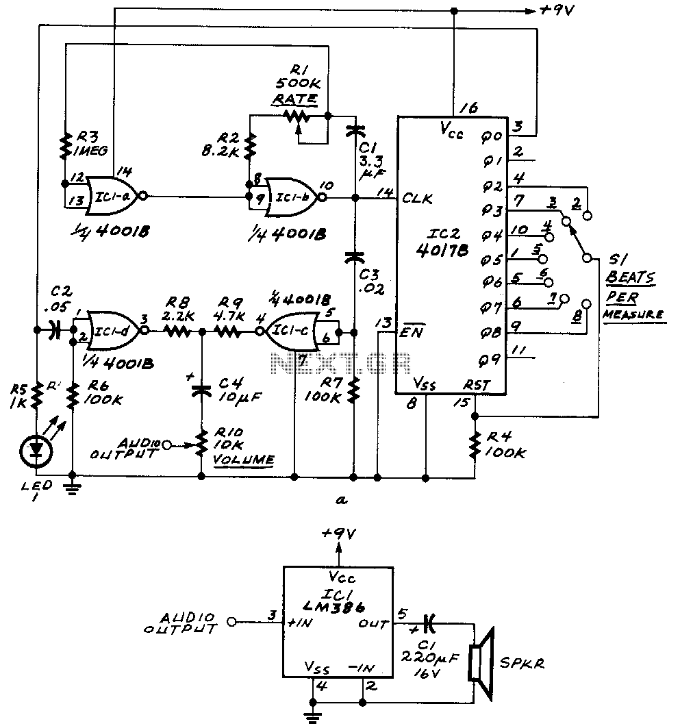
ICla and IClb form an astable multivibrator. The astable's signal is fed to IC1c, as well as to the clock input of IC2, a 4017B decade counter. The outputs Q0 through Q9 of that IC become high one at...
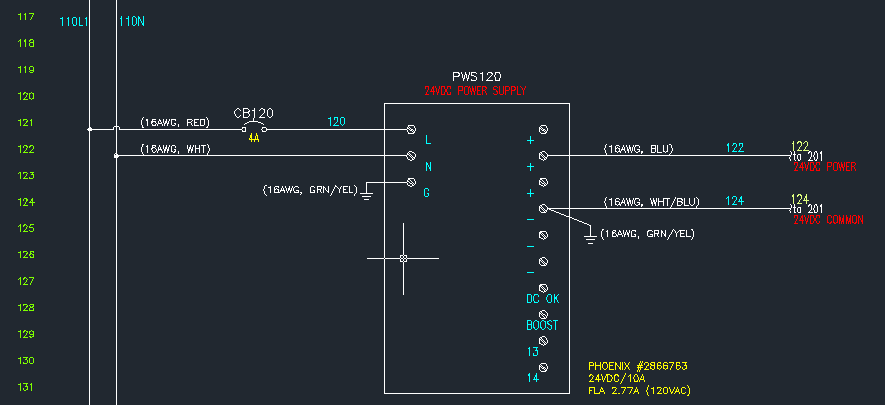
The power supply unit (PSU) in question does not appear to be exceptionally large. Eagle software should be capable of managing these dimensions. The focus was more on finding an alternative that may already include the necessary components and...
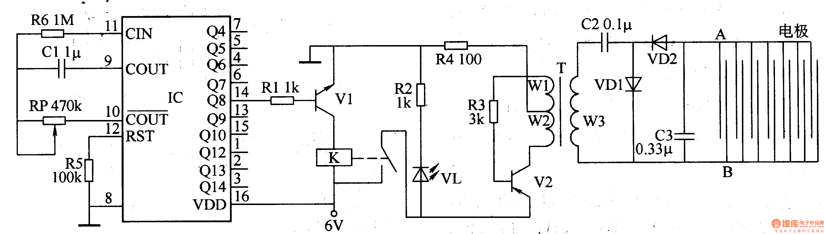
The electronic locust killer device consists of a square wave oscillator circuit and a high-voltage generator circuit, as illustrated in Figure 3-192. The square wave oscillator comprises a counting divider IC, resistors R5 and R6, capacitor C1, and potentiometer...
Touch operated switches are an attractive project for DIY electronics but they are not so common in commercial products. The reason for this is that, although there are many different ways of implementing a touch switch (leakage, hum pickup,...