
two-tone generator

The Wien bridge oscillator is a widely used circuit for generating sine waves, characterized by its simplicity and effectiveness. In this configuration, the two 741 operational amplifiers (or the 1458 dual op-amp) play crucial roles in establishing the oscillation frequency and maintaining stability. The oscillator circuit is designed to operate within a frequency range of 500 to 2000 Hz, ensuring that the selected frequencies do not exhibit harmonic relationships, which could lead to distortion in the output waveform.
In the circuit, the first operational amplifier, U1A, is configured to set the output level through a resistive divider network. This arrangement allows for precise control over the amplitude of the signal generated by U1A. The second operational amplifier, U1B, features an adjustable output, which is controlled by the variable resistor Rl. This adjustability is essential for fine-tuning the oscillator's performance and ensuring that the output remains stable.
The outputs from both U1A and U1B are combined in the third operational amplifier, U2, which acts as an adder with unity gain. This configuration allows for the summation of the two oscillating signals, resulting in a composite output that retains the desired characteristics of both oscillators. The final output from U2 can be adjusted further using resistor R2, providing an additional level of control over the amplitude of the output signal.
Overall, this Wien bridge oscillator design effectively utilizes operational amplifiers to generate stable sine wave outputs across a specified frequency range, making it suitable for various applications in signal generation and waveform synthesis.Two 741 operational amplifiers are used for the active element in this Wien bridge oscillator. (The 1458 is the dual version of the 741.) Frequencies of the two oscillators were chosen to fit standard component values. Other frequencies between 500 and 2000 Hz can be employed. They should not be harmonically related. The output level of U1A is set by a resistive divider, while the output of U1B is adjustable through Rl. The output of the two oscillators is combined in U2, an op-amp adder with unity gain. The output from U2 can be adjusted using R2.
Related Circuits
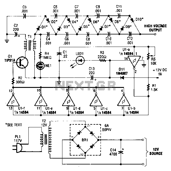
This circuit is powered by a 12-V DC power supply. The input to the circuit is amplified to generate a 10,000-V DC output. The output of the up-converter is subsequently directed into a 10-stage high-voltage multiplier to achieve a...

The two circuits illustrate the generation of low-frequency sine waves by shifting the phase of the signal through an RC network, enabling oscillation when the total phase shift reaches 360 degrees. The transistor circuit on the right produces a...
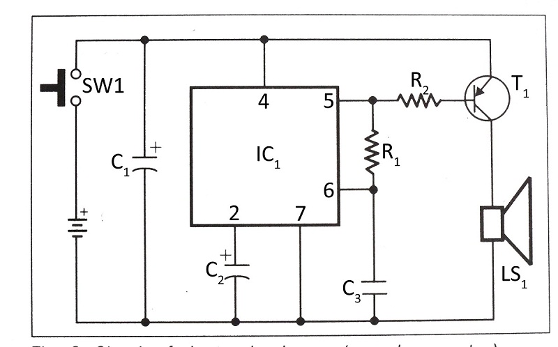
This document presents a verified circuit diagram for a simple, interesting, and cost-effective electronic clapper (sound generator) circuit, along with a description of its functionality. The electronic clapper circuit is designed to activate sound generation through the detection of sound...
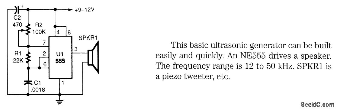
This basic ultrasonic generator can be built easily and quickly. An NE555 drives a speaker. The frequency range is 12 to 50 kHz. SPKRI is a piezo tweeter. The ultrasonic generator circuit utilizes the NE555 timer integrated circuit, which is...
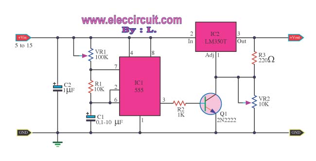
This is a Power Pulse Generator Circuit that utilizes the integrated circuit NE555 as a square wave oscillator generator. The frequency can be adjusted by varying resistor R1. The output from the NE555 is then sent to a transistor...
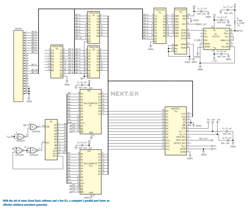
You can use the parallel port of your PC and a few additional components to generate a powerful, easy-to-use arbitrary-waveform generator. By using a Visual Basic program with the circuit in Figure 1, you can generate any waveform (for...