
Pulse Generator by IC LM350T and 555
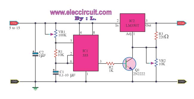
The Power Pulse Generator Circuit is designed for applications requiring precise control of voltage and current through pulse modulation. The NE555 timer is configured in astable mode to generate a continuous square wave output, which is determined by the resistances of R1 and the capacitor connected to the timing pins of the IC. The frequency of oscillation can be calculated using the formula:
\[ f = \frac{1.44}{(R1 + 2R2)C} \]
where R2 is another timing resistor and C is the timing capacitor.
The output from the NE555 is fed into the base of the 2N2222 transistor, which acts as a switch. When the NE555 output goes high, the transistor turns on, allowing current to flow through the LM350T voltage regulator. The LM350T is capable of providing adjustable output voltage, which can be set using R5. This voltage can be fine-tuned to achieve the desired output range from a minimum of 1.2V to a maximum of 15V, making this circuit versatile for various electronic applications.
The circuit requires a stable power supply within the specified input voltage range of 5V to 15V to ensure proper operation. The design emphasizes efficiency and reliability, making it suitable for use in power management systems, battery chargers, and other electronic devices that require a controlled pulsed output. Proper heat sinking should be considered for the LM350T when operating near its maximum current capacity to prevent thermal overload.This be Power Pulse Generator Circuit, by use the integrated circuit NE555 be Square wave Oscillator Generator. Fine the frequency done to a turn R1. From that time send output go to still transistor 2N2222 control give IC LM350T work have voltage come out the character pulse that have current tall about 3 Amp.
By friends fines R5 for control the level voltage, minimum 1. 2V by high class topmost pressure about 15V, because of this circuit uses input about 5V 15V. 🔗 External reference
Related Circuits
In this auto shut-off tone generator project, connecting the switch to the 9V power supply triggers an alarm that emits a frequency of approximately 1.27 kHz. The alarm remains active for about 170 seconds (or 2.8 minutes) before it...
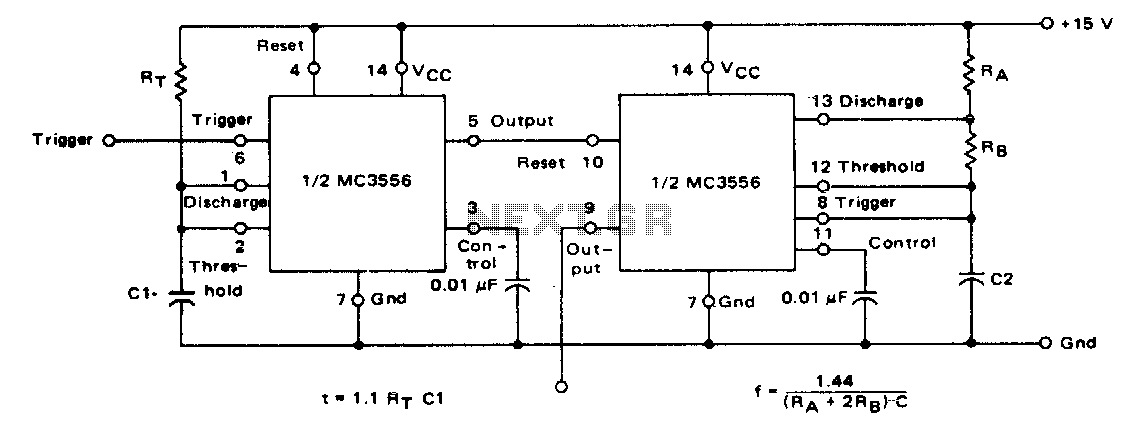
The first timer is used as a monostable and determines the tone duration when triggered by a positive pulse at pin 6. The second timer is enabled by the high output of the monostable. It is connected as an...
This circuit allows for the superimposition of a title and/or the time and date on an incoming video signal, which is particularly useful when editing video tapes. With the advent of affordable CCD camera modules, setting up a personal...
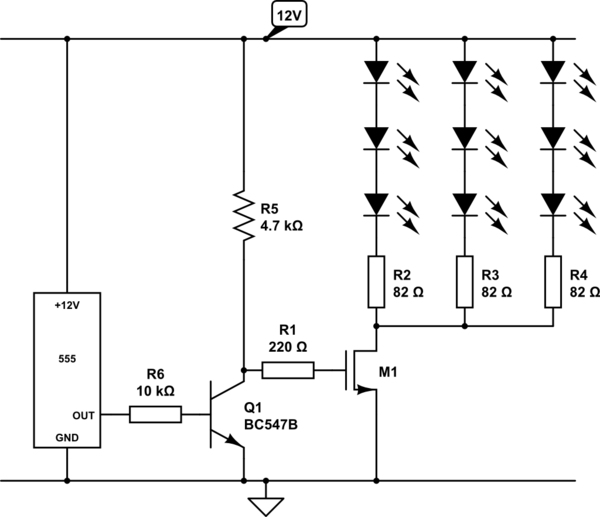
Create a circuit using a 555 timer to operate 72 LEDs simultaneously. A circuit has already been constructed, but there are concerns regarding its safety and longevity. A picture of the circuit is provided for review, and assistance is...
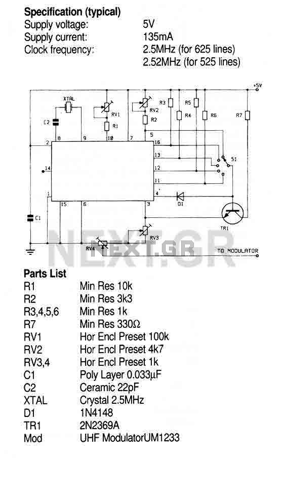
This Circuit uses the ZNA234E IC which makes available all the waveforms necessary to produce the crosshatch, dot and greyscale test patterns on a television screen. The composite video output can be injected directly into the video input of...
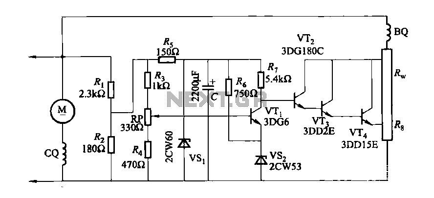
The DC generator automatic voltage regulator circuit is illustrated in Figure 7-53. This circuit is designed for a 40kW, 230V DC shunt complex machine, with a voltage change rate of up to 2.5 percent. In Figure 7-53, BQ represents...