
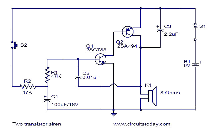
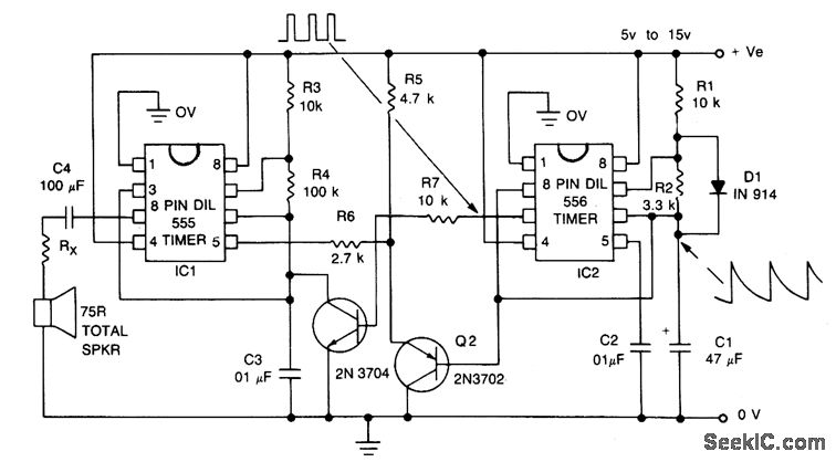
Two transistor siren
The described two-transistor alarm circuit operates effectively as a simple oscillator, utilizing the characteristics of the transistors and the RC timing components. The circuit comprises two NPN transistors, typically configured in a feedback arrangement to sustain oscillation. The charging and discharging of capacitor C1 through resistor R2 creates a varying voltage that influences the base of Q1, thereby modulating the frequency of oscillation.
In practical implementation, when switch S2 is pressed, the circuit initiates oscillation as C1 begins to charge. The rapid increase in voltage across C1 reduces the RC time constant, which accelerates the oscillation frequency. This results in a higher-pitched sound emitted from the connected speaker, akin to a siren. The design can be adjusted by varying the values of R2 and C1 to achieve different frequency ranges based on desired application requirements.
Upon releasing switch S2, the capacitor C1 discharges, and the frequency of the oscillation decreases, producing a lower-pitched sound. The performance of the alarm circuit can be influenced by the selection of components, including the transistors, which should be chosen based on their switching speed and gain characteristics to ensure reliable operation.
This circuit serves as an effective and educational example of using basic electronic components to create sound-producing devices, demonstrating principles of oscillation, capacitance, and resistance in practical applications. It can be utilized in various alarm systems, toy applications, or as a learning tool for understanding oscillator circuits in electronics.Here is the circuit diagram of a simple two transistor alarm circuit that can be operated from a 9V PP3 battery. Here the two transistors are wired to form an oscillator whose frequency increases when switch S2 is pressed and decreases when S2 is released.
In order to attain this the base of Q1 is biased from an RC circuit comprising of R2 and C1. When S2 is pressed C1 is charged through the resistor R2. As the voltage across the C1 increases the time constant decreases and this results in an increases in the frequency. When S2 is released capacitor discharges and the frequency of the tone decreases. The sound heard from the speaker will be almost like that of a siren. 🔗 External reference
Related Circuits
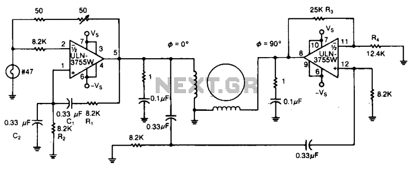
Due to its high amplification factor and integrated power-output stage, an integrated power operational amplifier serves as an effective driver for AC motors. One operational amplifier can be configured as an oscillator to generate the necessary AC signal. The...
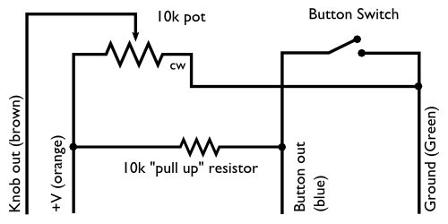
Tennis for Two displayed a side-view of a tennis court on an oscilloscope screen, allowing two players to toss a ball to each other using handheld controllers. Each controller featured two controls: a button and a knob. The button...
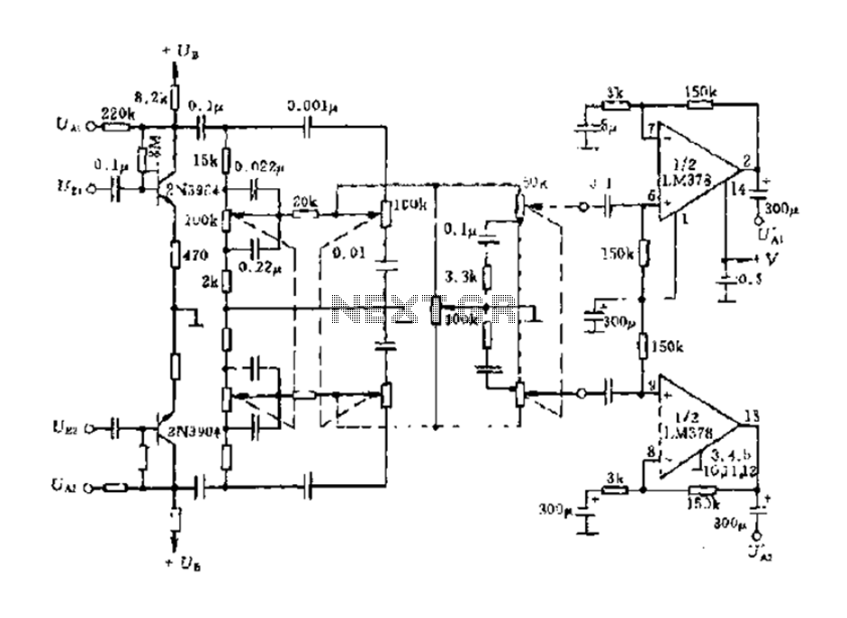
The dual-channel circuit features the LM378 dual operational amplifier and operates with a supply voltage of 24V, supporting an 8-ohm load (or 16 ohms). Each channel delivers an output power of 4W. The circuit includes internal current limiting and...
The signal begins at a low frequency, increases over approximately 1.15 seconds to a high frequency, pauses for about 0.35 seconds, and then starts to rise again from a low frequency, continuing this pattern indefinitely. The described signal exhibits a...
The circuit was designed to create an electronic siren to produce an alert sound in emergency situations or any circumstances that require its usage. The 4011 is a quad 2-input NAND gate integrated circuit, characterized by minimal voltage supply...

Sustainable satellite 802.11b wireless internetwork and how it was achieved. The design of a sustainable satellite 802.11b wireless internetwork involves the integration of satellite communication technology with wireless networking standards to create a robust and efficient communication system. This architecture...