
Two Tube AM Transmitter

The AM transmitter circuit described is an example of a classic design that utilizes vacuum tubes for signal generation and modulation. The 6SA7 tube, functioning as a mixer and oscillator, is critical in creating the AM signal. Its operation hinges on the interaction between the grid and plate currents, which modulate the signal based on the audio input. The design's use of an LC circuit for frequency stability and modulation is a hallmark of analog transmitter designs, allowing for fine-tuning of both frequency and output power.
The 6888 tube's unique structure enables it to serve dual roles, enhancing the transmitter's performance. The inclusion of a crystal oscillator not only stabilizes the frequency but also simplifies the design by eliminating the need for external frequency control components. The careful selection of components such as the trimmer capacitor and the zener diode ensures that the transmitter operates efficiently and safely.
Safety precautions are paramount in this design, particularly regarding the power supply and grounding. The recommendation for an isolation transformer is critical in preventing electrical hazards, especially in a home-built transmitter where the risk of accidental miswiring exists. Overall, this AM transmitter design reflects a blend of traditional techniques with modern safety considerations, making it suitable for hobbyists and educational purposes.I finally completed a working AM transmitter. The transmitter`s design is based on several ideas, but mainly based on Phil`s Li`l 7 Transmitter design. It is not always easy to achieve oscillation in LC-based transmitters without the right combination of tubes and coils.
The tubes used in this transmitter is a 6J5 and 6SA7 th at operates at around 1400kHz on the AM band. Below is the schematic diagram of the transmitter. The antenna coil was salvaged from the oscillator circuit in a typical old radio with a 455kHz I. F. frequency. The coil generally has two windings; one with a larger DC resistance than the other and is indicated as the larger winding in the schematic. If there is no oscillation present on the antenna of the 6SA7 then reversing the connections to one of the coil windings usually does the trick.
The plate current by the 6SA7 causes the larger winding to generate a magnetic field that induces current in the other coil. The coil has to be the correct polarity to push the grid negative to reduce plate current. When the plate current reduces then the grid current reduces and allows more plate current to flow. The oscillations are controlled by the LC circuit consisting of the grid coil and the 150pF capacitor.
The trimmer capacitor in parallel with the 150pF allows small range adjustment of the carrier frequency. If oscillations do not start, flipping around windings might help. Modulation is achieved by feeding audio in the second grid of the 6SA7 tube so the plate current is controlled by the audio signal.
As a result, the oscillator signal and the audio signal are superimposed upon each other resulting in an amplitude modulated signal, hence it is an AM transmitter! The 6J5 is a triode designed for general purposes, but in this transmitter it serves as a low power half-wave rectifier in this circuit.
The power supply provides about 140VDC loaded. The 6J5 was one of the few tubes I could find in my junk box at the time, but I would recommend using a tube that is actually designed for rectification purposes such as a 6X4. BEWARE! An isolation transformer or some sort of power transformer is highly recommended because one side of mains is connected to the ground side of the audio input.
The plug must be polarized so this side of the circuit sees the neutral. If the plug were accidently reversed and the ground shield of the audio cable were to become hot then it could potentially SHORT out with most, if not all, AC powered audio equipment. I only use a portable CD player or audio device with this transmitter to avoid conflicts with AC polarity.
Some fellow ARF ( Antique Radio Forum ) members offered to send me some parts to get started on a quite successful 6888-based AM transmitter. The 6888 is an oddball octal tube that goes by the description of "dual control pentode" because its first grid and supressor grid both are used as a control grid.
In the kit design, a 6AB4 or 6C4 is used as an audio preamp and the 6888 as the transmitting tube. Below is a schematic of the transmitter as designed by members on ARF. The circuit is fairly straight forward for a transmitter but there are some noteworthy features. The 1MHz crystal oscillator requires 5 volts and produces a nice square wave output at 1MHz. These oscillators are normally used in TTL or computer circuits because it is a self-contained oscillator rather than a mere crystal. The cathode current by the 6888 is sufficient to provide power to the crystal oscillator and a 1N4733 (5V 1W zener) is used to regulate the voltage.
The oscillator output controls the first grid of the 6888 to create a clean 1MHz carrier on the plate. The inductor and trimmer capacitor above the plate of the 6888 serves as a tuned LC tank. The trimmer capacitor will adjust the output strength and thereby the range of the transmitter. The range is largest when the LC circuit resonates at 1MHz. For use with st 🔗 External reference
Related Circuits
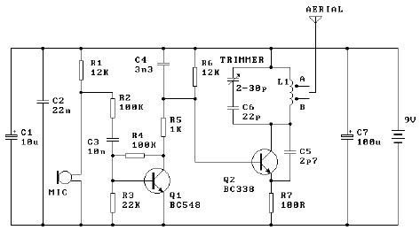
The tuned coil L1 has two output tap points for the antenna connection, labeled "A" and "B." Both outputs are low-level, allowing the user to select between a stable low range or a more unstable but higher range. Tap...
L1 is 0.112uH (this tunes to the middle of the FM band, 98 MHz, with VC1 at its centre value of 33pF). L1 is 5 turns of 22 swg enamelled copper wire close-wound on a 5mm (3/16") diameter former....
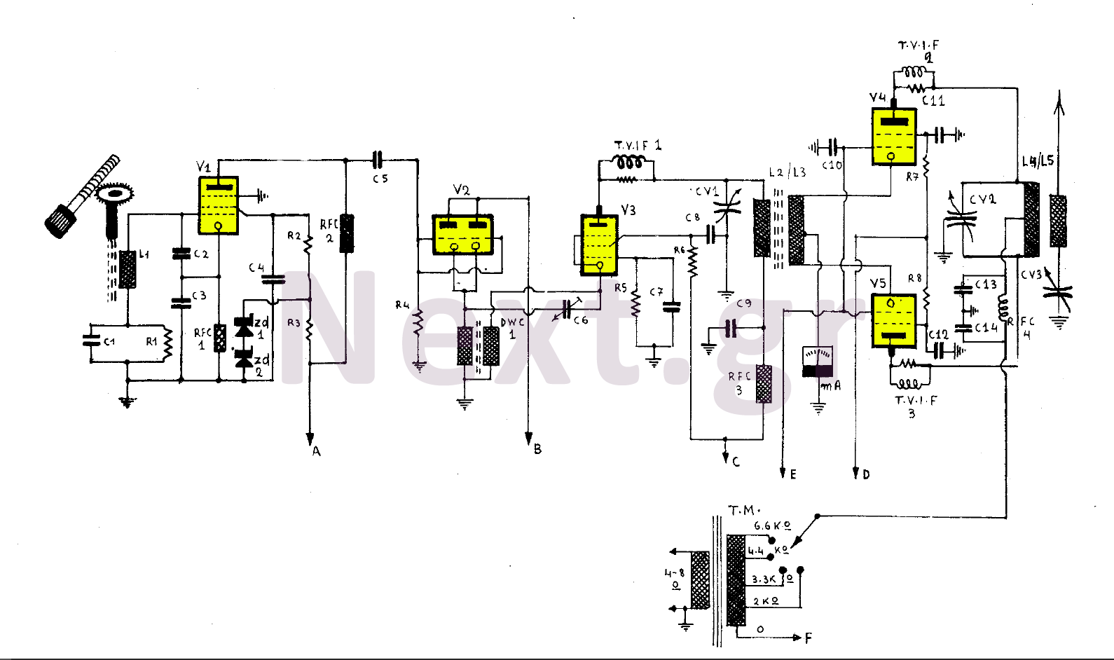
This 255W transmitter operates using coils designed for both medium and short waves. The antenna power is set at 255W and includes four operational states. The first state utilizes an EF80 tube functioning as a Colpitts Clapp oscillator. Frequency...
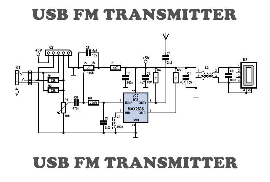
To test VHF receivers independently from local radio stations, a frequency-modulated oscillator is required, covering the range of 89.5 to 108 MHz. Building such an oscillator with discrete components is challenging. The MAX260x series from Maxim offers five integrated...
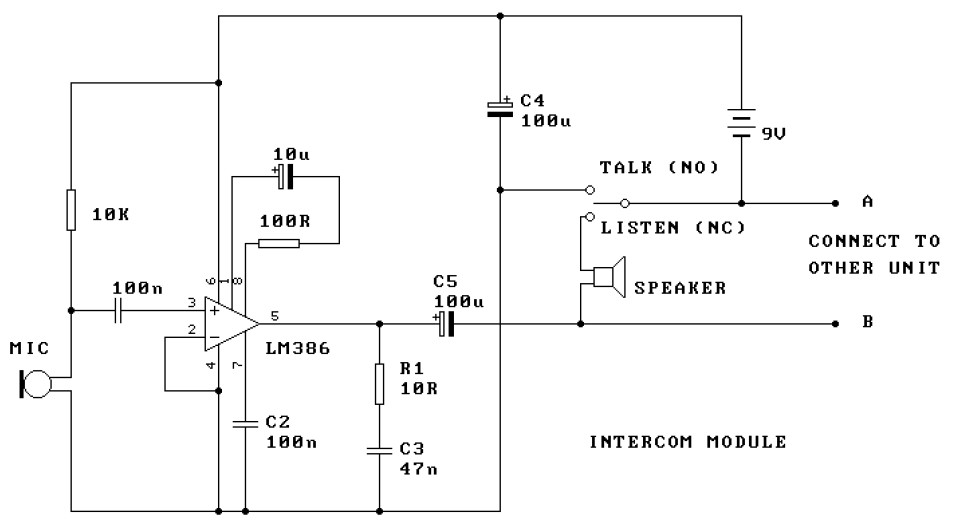
This is a two-station intercom system that operates using two wires connecting each intercom unit. Each unit is self-contained, equipped with its own battery, speaker, microphone, and amplifier circuit. An LM386 audio power amplifier is utilized, which is widely...
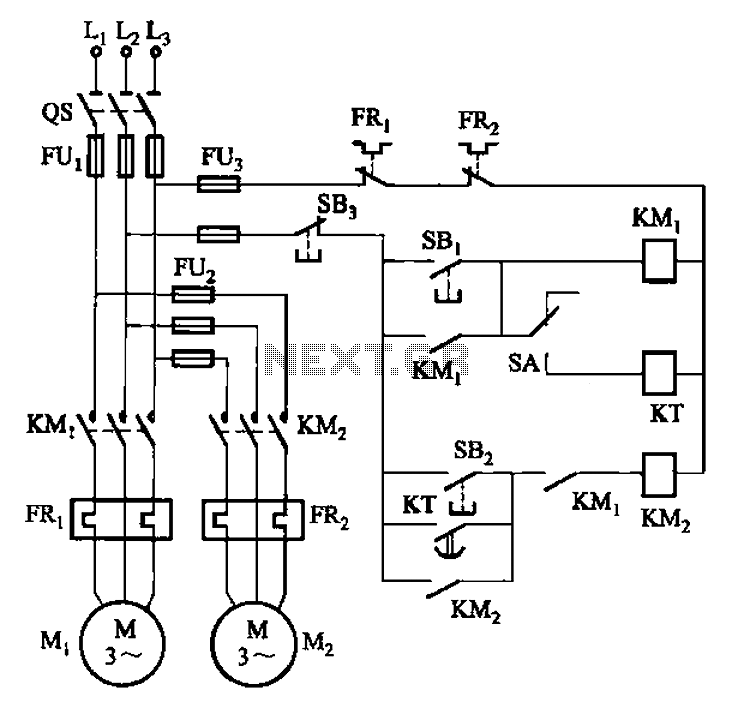
The circuit illustrated in Figure 3-85 features both manual and automatic control through the transfer switch SA. After initiating the motor Mi, an automatic start sequence is achieved via the time relay KT. The circuit employs a transfer switch (SA)...