
FM Transmitter Circuit

The circuit described utilizes an inductor (L1) of 0.112 microhenries, designed to resonate at a frequency of approximately 98 MHz, which corresponds to the center of the FM broadcast band. This inductor is constructed from five turns of 22 SWG (Standard Wire Gauge) enamelled copper wire, wound closely around a 5 mm diameter former. The use of a variable capacitor (VC1) with a nominal value of 33 picofarads allows for fine-tuning of the oscillator frequency, providing a tuning range from 85 MHz to 125 MHz. An alternative configuration can employ a fixed capacitor instead of VC1, utilizing an adjustable molded coil such as the UF64U from Maplin.
For precise tuning, the Philips type polypropylene film trimmer (Maplin code WL72P) is recommended, ensuring optimal performance across the desired frequency range. The circuit features two sets of bias resistors for the oscillator, with one set providing approximately 20% more RF power, which may be beneficial for applications requiring increased signal strength.
The microphone used in this circuit is an omnidirectional sub-miniature electret (Maplin code FS43W), which is well-suited for capturing audio signals. The antenna configuration is a quarter-wavelength monopole, constructed from approximately 76 cm of 22 SWG copper wire, which ensures effective transmission of the modulated signal.
The transistor Q1 operates as a Clapp oscillator, a configuration known for its frequency stability and low phase noise. The frequency modulation is achieved through variations in the audio voltage, which alters the base-emitter capacitance of the transistor, thereby modulating the output frequency in accordance with the input audio signal. This design is particularly effective for FM transmission applications, providing clear and stable audio output.L1 is 0.112uH (this tunes to the middle of the FM band, 98 MHz, with VC1 at its centre value of 33pF). L1 is 5 turns of 22 swg enamelled copper wire close-wound on a 5mm (3/16") diameter former. Alternatively, you can have a fixed 33pF cap instead of VC1 and have L1 as an adjustable molded coil (eg UF64U from Maplin).
VC1 will give you a tuning range of 85 - 125 MHz, and a possible choice is the Philips type polypropylene film trimmer (Maplin code WL72P). Two sets of oscillator bias resistors are given, the ones in the brackets give about 20% more RF power.
Mike is our favourite Omnidirectional sub-mini electret (Maplin code FS43W). Ant is a (lambda / 4) whip monopole (eg 76 cms of 22 swg copper wire). Q1 is configured as a Clapp oscillator. Frequency modulation results from the audio voltage changing the transistor`s base-emitter capacitance. 🔗 External reference
Related Circuits

This compact FM transmitter has a range of approximately 50 meters and is designed for hobbyists. With multiple mini-transmitters, users can create a diverse and engaging radio program. The device achieves high frequency stability due to its power supply...
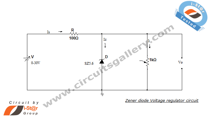
A Zener diode regulator is a fundamental electronic circuit valuable for hobbyists. This circuit provides a regulated output voltage, suitable for biasing other circuit components. The Zener diode operates in the reverse breakdown region, maintaining a nearly constant voltage...
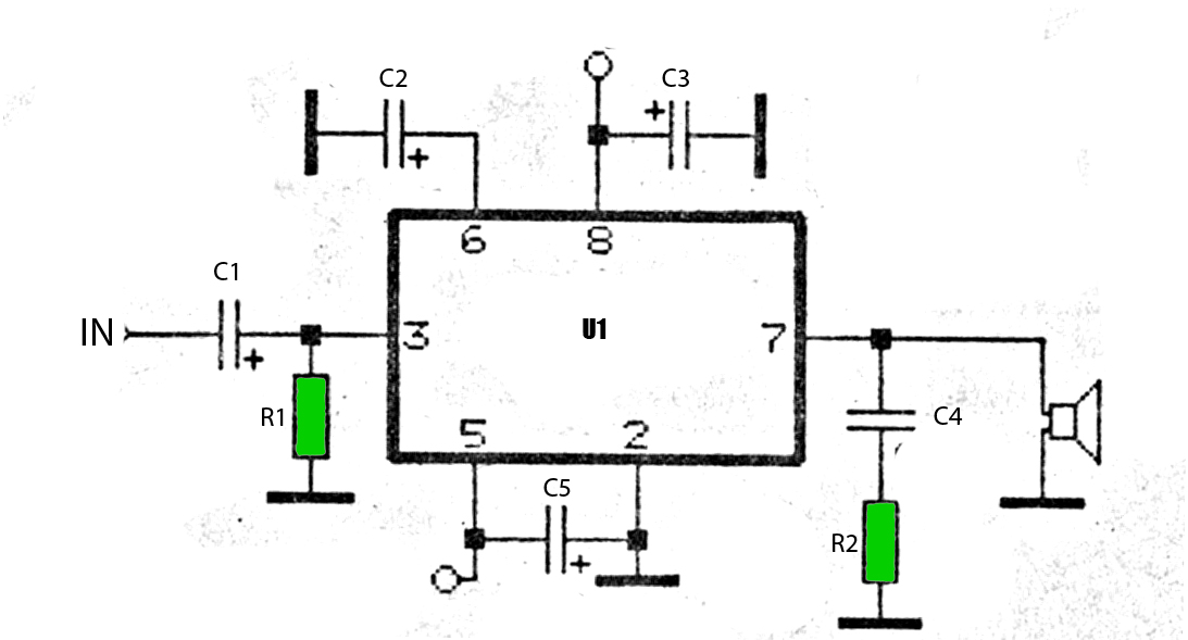
The car power amplifier utilizes the SI1050GL integrated circuit (IC) as the primary amplification component. It delivers an output power of 50 Watts at an 8-ohm mono impedance. The amplifier operates with a DC voltage of up to 25...
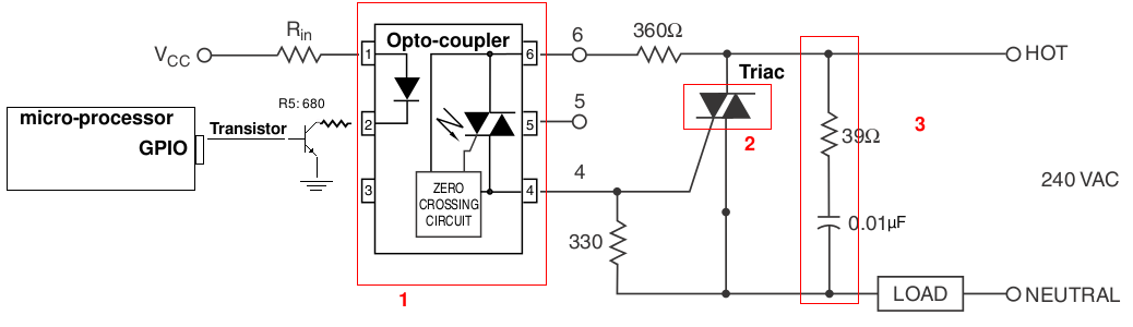
A light-dimming control system is being developed for a 240V heat lamp with a power dissipation of approximately 250W. The objective is to adjust the heat output of the lamp using control from a microprocessor. The development is based...
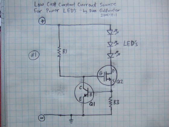
Here is a simple and cost-effective Power LED driver circuit. This power LED driver circuit is designed to efficiently drive high-power LEDs with a stable output. The circuit typically consists of a few key components: a power supply, a current...
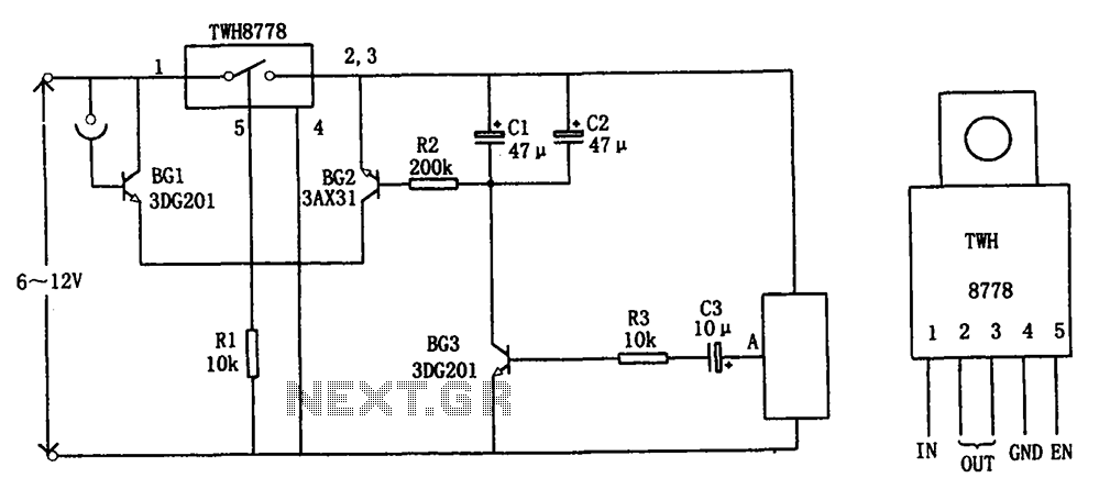
The circuit illustrated in FIG X pertains to automatic circuitry for US recorders. It primarily utilizes a new power switching device, TWH8778, which simplifies the design and eliminates the need for extensive debugging. The TWH8778's configuration and pin functions...