
AC motor control circuit sprinkler

The AC motor control circuit for a sprinkler system is designed to regulate the operation of an AC motor, which drives the sprinkler mechanism. The circuit typically includes several key components: a power supply, a motor driver, control switches, and safety features such as fuses or circuit breakers.
The power supply provides the necessary voltage and current to the AC motor. It is essential to select a power supply that matches the motor specifications to ensure efficient operation. The motor driver is responsible for controlling the motor's speed and direction. This can be achieved through various methods, including using relays or solid-state switches.
Control switches are integrated into the circuit to allow the user to start or stop the motor and set the desired operating parameters. These switches can be manual or automated, depending on the system design. For instance, a timer switch can be used to activate the motor at predetermined intervals, facilitating automated watering schedules.
Safety features are critical in protecting both the motor and the circuit from overcurrent or short circuits. Fuses or circuit breakers should be strategically placed within the circuit to disconnect the power in the event of a fault, thereby preventing damage to the components.
The overall design of the AC motor control circuit should adhere to electrical safety standards and regulations, ensuring reliable operation while minimizing the risk of electrical hazards. Proper grounding and insulation are also vital to protect users and equipment from electrical shock.
In summary, the AC motor control circuit for a sprinkler system is a carefully designed assembly of components that work together to automate the watering process, ensuring efficiency and safety in operation.AC motor control circuit sprinkler If the circuit in the motor is an AC motor can be designed according to the circuit shown in FIG connection, work process and the principle o f the circuit with the procedure described above.
Related Circuits
This circuit operates at potentially lethal 220V AC mains voltage. The circuit should be built and used only by individuals who know how to safely work with such dangerous voltages and how to construct the circuit to ensure safety....
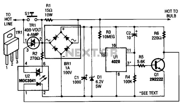
The automatic porch-light control circuit maintains a triac in an active state until a 4020 divider counts a series of 60-Hz power line pulses. This circuit is designed to turn off the light after a specified duration, utilizing pins...
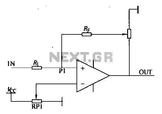
Environmental interference can affect the transfer switching, leading to the production of burrs in confidence disgrace. The switch position signal will control the computer system with the reliability of lanthanum burrs. The work has some impact. Glitches are typically...
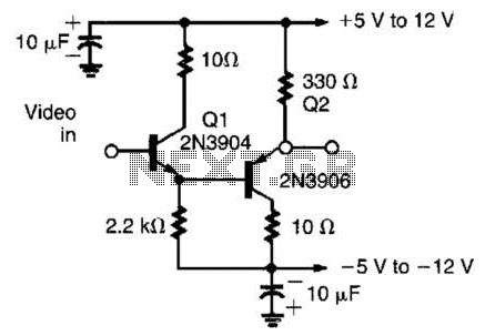
This circuit has demonstrated effectiveness as a video buffer and can easily drive a 75-ohm load to a 1.5-V peak-to-peak output. The bandwidth exceeds 20 MHz, and the DC offset is less than 0.05 V, attributed to the difference...
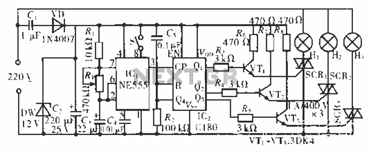
The circuit operates at 220 V AC using a C1 buck converter and a DW regulator. The VD ensures the entire stream is processed, and C2 provides a filtered output of 12 V DC for the voltage supply control...
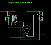
This is a simple intercom circuit utilizing the common IC LM380. In this configuration, the switch is set to the talk position for the speaker on the left, while the other participant is in the listening position. If the...