Automatic distress alarm kit control circuit

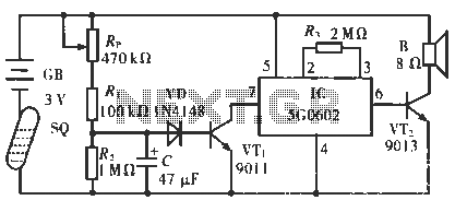
The circuit operates in such a way that when the patient is typically in an upright position, the SQ mercury switch is turned off, resulting in the alarm circuit being inactive. When the patient lies down, the SQ switch automatically connects to the power supply circuit, allowing the GB to charge capacitor C. After a few seconds, the charging voltage across capacitor C reaches approximately 1.3 V, activating diodes VD and VT in succession. This activation turns on the cutoff, which generates a low-level trigger signal at pin 7. The output pulse from pin 6 produces a frequency conversion signal, which is amplified by power amplifier VT2 to drive a buzzer, emitting a pleasant tone alarm.
The described circuit is a patient monitoring alarm system that utilizes a mercury switch to detect the patient's position. The SQ mercury switch is a crucial component that ensures the alarm remains off when the patient is upright, thereby preventing unnecessary alerts. When the patient lies down, the switch closes, initiating a series of events that lead to the activation of the alarm.
The circuit begins with the connection of the power supply to the GB, which is responsible for charging the capacitor C. The capacitor serves as a timing element in the circuit. Once the voltage across the capacitor reaches approximately 1.3 V, it enables the diodes VD and VT to conduct. This conduction is essential for the subsequent operation of the circuit, as it allows current to flow through the cutoff mechanism, which is responsible for generating a low-level trigger signal at pin 7.
The low-level trigger signal is a vital input for the pulse output at pin 6. This output is designed to produce a frequency conversion signal that modulates the alarm tone, creating a more pleasant sound for the user. The modulation is achieved through a frequency conversion process that alters the pitch or tone of the alarm, making it more effective in grabbing attention without being overly jarring.
The power amplifier VT2 plays a significant role in driving the buzzer. Its function is to amplify the pulse output signal so that the buzzer can produce a sound loud enough to be heard from a distance. The design of the circuit ensures that the alarm is activated only when necessary, thereby conserving power and reducing wear on the components.
Overall, this circuit exemplifies a thoughtful design aimed at enhancing patient safety by providing an alert system that activates based on the patient's position. The integration of the mercury switch, capacitor timing, and frequency modulation in the alarm sound ensures a reliable and effective monitoring solution.Circuit works: When the patient usually upright, packed in kit SQ mercury switch was turned off, the alarm circuit power does not work. Once the patient down, SQ automatically connected to the power supply circuit, GB by RT, charges C, after a few seconds about the charging voltage across C up to about 1.3 V, VD and VT. Successively by the cutoff turned ON, lC by 7 feet to get low-level trigger signal work, the output of the pulse output of 6 feet three frequency conversion signal, the VT2 power amplifier, the drive B issue a pleasant change tone alarm .


