
UHF amplifying circuit diagram

The UHF amplifying circuit is structured to enhance signals within the specified frequency range, making it suitable for various applications such as communication systems, broadcasting, and wireless transmission. The circuit typically includes components such as transistors, resistors, capacitors, and inductors, arranged to achieve the desired gain and bandwidth characteristics.
To construct the printed circuit board (PCB), it is essential to utilize high-quality materials that can support the operational frequencies. The use of silver-tin processing is particularly advantageous due to its superior conductivity and reliability, which contribute to lower signal loss and improved overall circuit performance.
The layout of the circuit should be designed to minimize parasitic capacitance and inductance, which can adversely affect the frequency response. Proper grounding techniques and careful routing of signal paths are critical to maintaining signal integrity. Additionally, the choice of components should be made with attention to their frequency response characteristics, ensuring that they can operate effectively within the 400 to 850 MHz range.
Thermal management is also a vital consideration, as amplifying circuits can generate heat during operation. Adequate heat dissipation methods, such as heat sinks or thermal vias, should be incorporated into the design to prevent overheating and ensure long-term reliability.
In conclusion, the UHF amplifying circuit designed for the 400 to 850 MHz frequency range requires careful consideration of material selection, circuit layout, and thermal management to achieve optimal performance. The recommendation for silver-tin processing further enhances the circuit's reliability and efficiency, making it suitable for high-performance applications.As shown in Fig range is a frequency of 400 ~ 850MHz UHF amplifying circuit. Printed circuit For best performance and results, the circuit should be used by the silver tin processing.
Related Circuits
Remove the 6 mm screw that secures the lower rear fairing cover. This cover is the black plastic piece to which the spark plug protectors are attached. Only the machine screw should be removed; do not detach the lower...
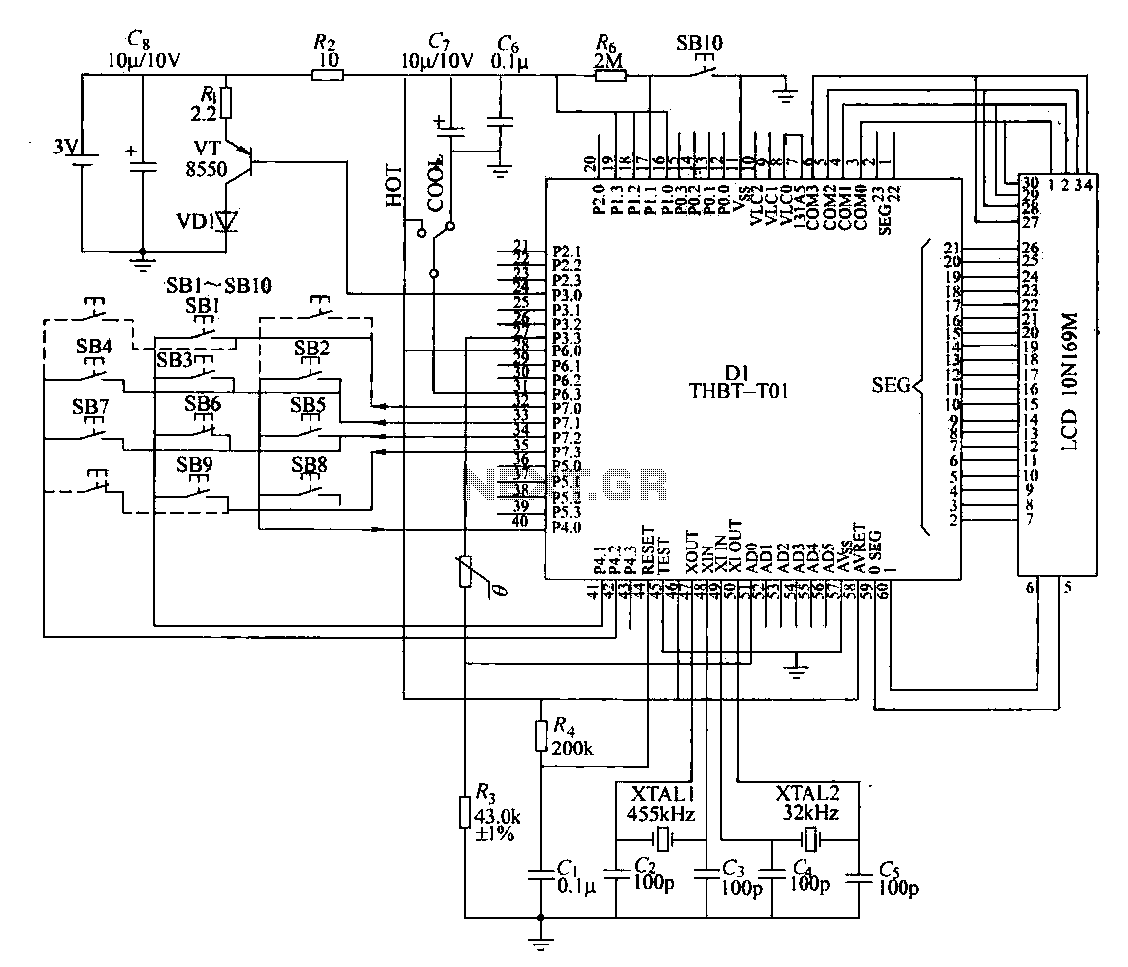
The circuit composition of a specific remote control transmitter is illustrated in a diagram. The transmitter primarily consists of a large-scale integrated circuit chip (D1, THBT-T01), a 4.5 kHz crystal oscillator, a 32 kHz crystal oscillator, a liquid crystal...
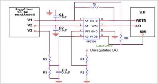
Introduction The SP6648 integrated synchronous boost regulator is a compact circuit that provides ultra-high efficiency drive current for an LED flashlight using a Luxeon I light source. The circuit is configured to deliver a constant output current of 350mA...
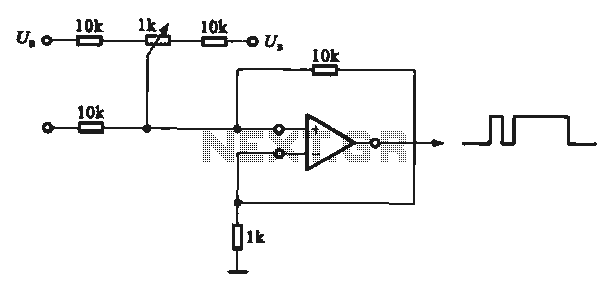
This circuit demonstrates the application of various types of pulse signal generating circuits using operational amplifiers. The circuit utilizes operational amplifiers (op-amps) to create different forms of pulse signals, which are essential in many electronic applications, including waveform generation, timing...
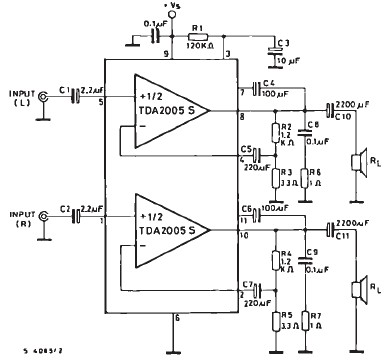
The TDA2005 car audio amplifier circuit is specifically designed for use in devices such as car radios and CD players. This amplifier circuit utilizes the TDA2005 audio integrated circuit (IC), which can deliver a maximum output power of 20...
Many households still use tube-type television sets. Connecting these large televisions to a stereo system to enhance sound quality is usually straightforward, as numerous SCART to Cinch adapters are available in accessory shops. However, some television sets may present...