
UHF TV Antenna Booster Circuit With BF180 Transistor

The UHF band TV antenna booster circuit is designed to enhance the signal strength received by UHF antennas, which are commonly used for digital television broadcasting. The circuit typically consists of a low-noise amplifier (LNA) that amplifies weak signals captured by the antenna. The gain of 15 dB indicates that the amplifier will increase the signal strength significantly, improving the quality of the received television signals and reducing the likelihood of pixelation or loss of picture.
The primary components of this circuit include the LNA, which is usually an integrated circuit (IC) designed for RF applications, along with passive components such as resistors, capacitors, and possibly an inductor for filtering purposes. The power supply for the circuit can be derived from a standard DC source, and it is essential to ensure that the voltage and current ratings are compatible with the LNA specifications.
The circuit layout should be designed to minimize interference and maintain signal integrity. This can be achieved by keeping the input and output traces short and using proper grounding techniques. Additionally, the use of a suitable enclosure can help shield the circuit from external electromagnetic interference.
To construct the antenna booster, the components should be assembled on a printed circuit board (PCB) or a perfboard, ensuring that all connections are secure and that the layout adheres to RF design principles. Once assembled, the circuit can be tested by connecting it to a UHF antenna and measuring the output signal strength using a signal strength meter or a compatible television receiver.
Overall, this UHF band TV antenna booster circuit offers a cost-effective solution for improving TV reception in areas with weak signal coverage, making it a valuable addition to any home entertainment system.This is a very simple circuit of UHF band TV antenna booster with 15dB gain power. This low cost antenna booster is simple and easy to build. This .. 🔗 External reference
Related Circuits
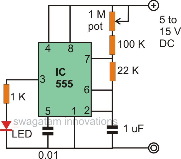
The astable multivibrator mode is the most basic operational mode of the IC 555. In this mode, it functions as a free-running oscillator. When the oscillator rate is sufficiently reduced, it can be used to drive LED lights. The...
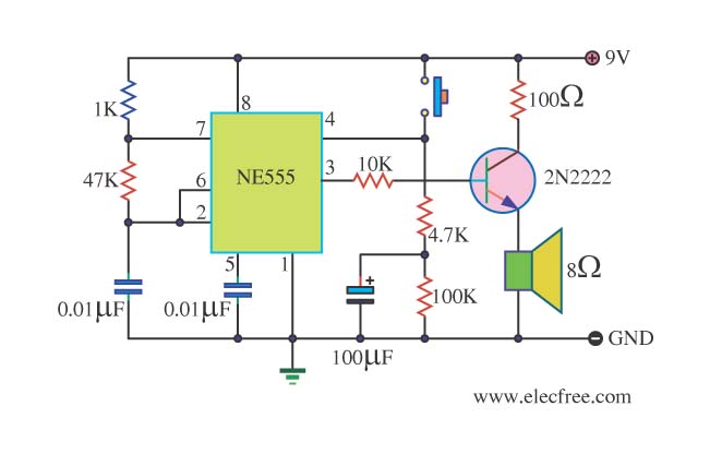
This is a danger beep circuit. It uses a 555 integrated circuit configured as a stable multivibrator that provides a duty cycle of 5% to drive a loudspeaker. The danger beep circuit utilizes the 555 timer IC, a versatile and...
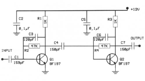
The following circuit illustrates a 20 dB VHF amplifier circuit diagram utilizing the BF197 transistor. Features include a simple circuit design. The 20 dB VHF amplifier circuit is designed to amplify very high frequency signals, making it suitable for applications...
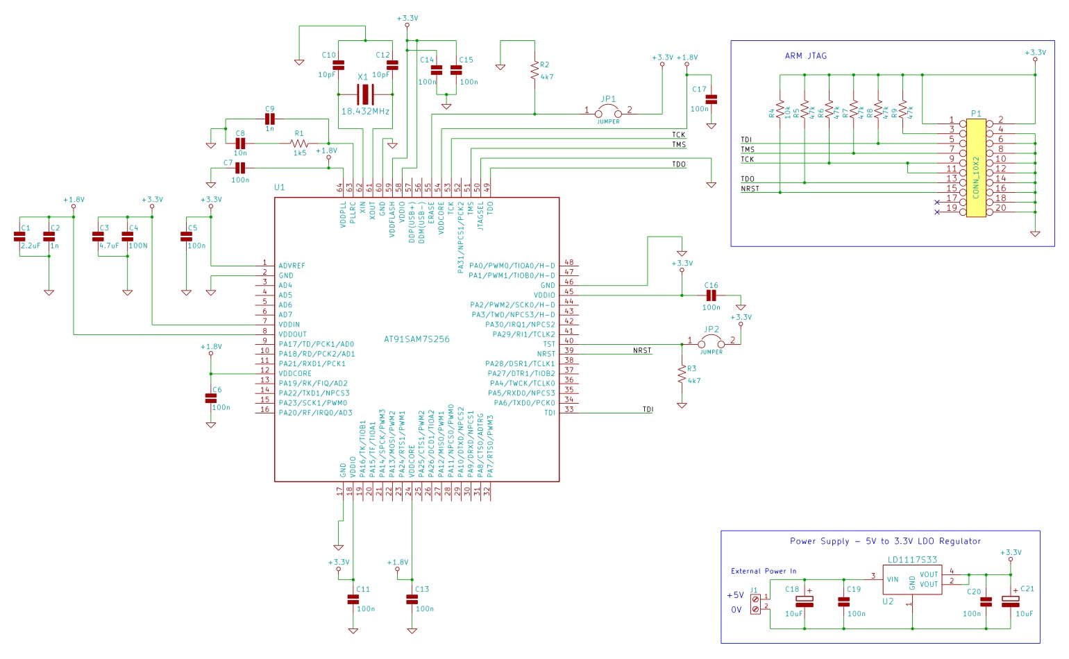
The minimum number of supporting components required to build a circuit using AT91SAM7S microcontrollers. This example uses the AT91SAM7S256 ARM7 microcontroller. To construct a circuit utilizing the AT91SAM7S256 ARM7 microcontroller, a minimal set of supporting components is essential to ensure...
A 100 second delayed turn ON relay RL1 switch, if plug power +12V in circuit. In Fig.2 see a two range 6-60 second and 1-10 minute auto turn off relay timer circuit, with 555. Part List R1=1 Mohms C4=100nF...
Although a hold feature is standard on most new phones, many users still utilize the original bell phones. For those who require a hold feature, this circuit is particularly useful. It is easy to construct and compact enough to...