
Common Base vs Common Emitter - Single Transistor Amplifier

The single transistor amplifier is a fundamental building block in electronic circuits, and its configurations—common base and common emitter—serve distinct purposes. The common base configuration is characterized by its input signal applied to the emitter terminal, while the output is taken from the collector. This configuration is known for its high frequency response and low input impedance, making it suitable for applications where these characteristics are essential.
In contrast, the common emitter configuration has the input signal applied to the base terminal, with the output taken from the collector. This configuration is widely used due to its ability to provide voltage gain and phase inversion, making it ideal for various amplification tasks in audio and radio frequency applications. The common emitter setup typically exhibits higher input impedance and lower output impedance compared to the common base configuration.
When comparing the two configurations, it is important to consider parameters such as voltage gain, current gain, and bandwidth. The common emitter configuration generally offers greater voltage gain, while the common base configuration excels in high-frequency applications due to its lower capacitance effects. Each configuration has its advantages and is chosen based on the specific requirements of the circuit design.
In practical applications, careful consideration of biasing, load resistance, and coupling methods is essential to optimize performance and stability. The choice between common base and common emitter configurations ultimately depends on the desired application, whether it be for signal amplification, impedance matching, or frequency response optimization.Single Transistor Amplifier Revisited Part 3, Common Base vs Common Emitter Configuration, Update One nagging question that I have long had is this: How do.. 🔗 External reference
Related Circuits
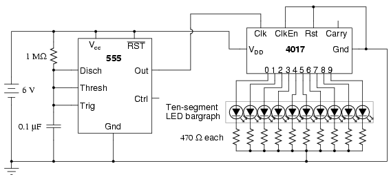
The following circuit illustrates a schematic diagram of an LED sequencer. This circuit is based on the 555 timer integrated circuit (IC). Features include a 555 timer circuit designed to debounce a mechanical switch, a 555 timer circuit to...
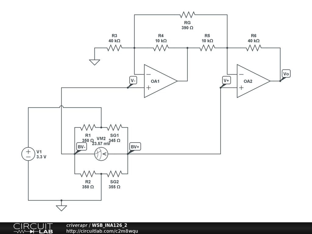
A half-bridge setup is utilized with strain gauges and an INA126 to amplify the voltage. The voltage can be read accurately when the lever is bent in one direction; however, no reading is obtained when the lever is bent...
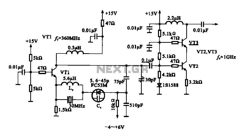
A variable frequency oscillator transistor circuit, primarily functioning as an oscillator, incorporates a crystal resonator and a varactor diode. The output is amplified, typically used for generating high-frequency signals. This 30 MHz transistor circuit features an inductor (LP) connected...
The circuit is based on a simple inductor-capacitor filter circuit, and needs only a pot and a small light bulb to set and stabilise the oscillation. The frequency is fixed, and with a good inductor should be capable of...
This paper describes an RF amplifier circuit which is suitable for the frequencies between 10MHz and 500MHz. These kind of amplifiers are called wide band amplifiers. Wide band amplifiers are used in communication receivers, RF measuring equipment and tons...
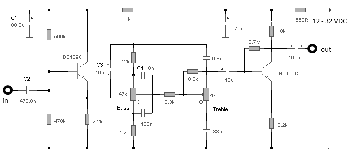
The first BC109C transistor functions as a buffer, offering the circuit an input impedance of approximately 250,000 ohms and a voltage gain just below unity. As the Baxandall tone control circuit is a passive design, it attenuates all audio...