
Ultra Low Power LCD Indicator

The circuit utilizes a 7555 integrated circuit, which is a CMOS variant of the 555 timer, to generate a square wave clock signal at a frequency of approximately 60 Hz. This clock signal is essential for driving the LCD display, ensuring that the visual output is dynamic and easily interpretable in various lighting conditions, particularly in full daylight. The LCD display is configured to show four bits of information, utilizing a total of 23 segments across three digits with two decimal points, thus providing a versatile platform for visual indicators.
The configuration of the display allows for multiple combinations of segment activation to represent different states or information. In the described setup, three squares and three lower segments are used to create four distinct indicators. This modular approach enables the designer to customize the visual output, potentially hard-wiring specific numbers or letters, or employing alternative LCD displays to achieve different visual effects.
The integration of four CMOS 4070 XOR gates plays a crucial role in the logic of the circuit. The output of each XOR gate is determined by the state of its inputs. When the secondary input to an XOR gate (ind*) is low, the output reflects the state of the primary input, facilitating the control of the segments displayed on the LCD. The XOR gates provide a simple yet effective means of toggling the displayed information based on the clock signal generated by the 7555 timer, thereby enabling real-time updates to the indicators as needed. This design exemplifies an efficient use of low-power components to achieve a functional and user-friendly display system.This circuit serves as an ultra-low power replacement for multiple LED on-off indicators. It also has the advantage of being easy to read in full daylight. With the parts shown, it is possible to display four bits of information. The display that I used has three digits and 2 decimal points for a total of 23 segments. Different groupings of segments can be used for the four indicators. I chose to use three squares (shown) and the three lower segments together (not shown) for the four indicators. Many other combinations could be used, one possibility would be to hard-wire numbers or letters out of each of the digits.
Other LCD displays could also be used for different effects. The 7555 IC (CMOS 555 timer) generates a square wave clock signal at approximately 60 hz. This signal is sent to the LCD backplane and the inputs of the four CMOS 4070 XOR gates. If the other input (ind*) of an XOR gate is low, the gate`s output is a 🔗 External reference
Related Circuits
This audio power amplifier is highly suitable for portable devices or as a headphone amplifier. The circuit design of this audio power amplifier is straightforward. This audio power amplifier circuit is designed to enhance audio signals for portable devices and...
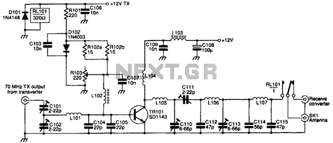
The SD1143 transistor offers a gain of approximately 14 dB in this circuit. Its design takes advantage of the fact that a 175-MHz device exhibits significantly higher gain when operated at lower frequencies. The amplifier was initially intended for...

This is a linear amplifier that requires advanced knowledge in electronics due to the complexity of the schematic diagram for a handmade circuit. It is advisable to redesign the schematic diagram using circuit design software such as DipTrace, Eagle,...
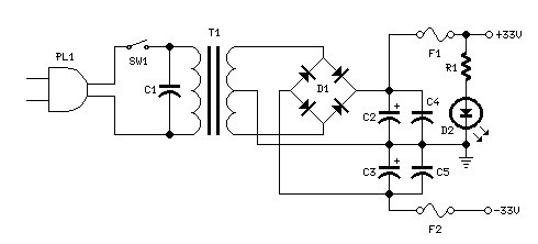
Power supply for a 25W power amplifier based on a MOSFET design. This power supply circuit is paired with a high-power audio amplifier rated at 1500 watts. The design of the power supply for the amplifier requires careful consideration....
The circuit was designed to increase an input signal of 4 Watts to 6 Watts, operating within the VHF radio frequency band, specifically for FM transmission. This circuit is engineered to amplify radio frequency signals in the VHF band, which...
The supply voltage should be about +/- 35 Volts at full load, which will let this little guy provide a maximum of 56 Watts (rated minimum output at 25 degrees C). To enable maximum power, it is important to...