
ultra miniature transmitter

This compact transmitter circuit is designed for simplicity and efficiency, making it an ideal project for hobbyists and beginners in electronics. The core of the circuit consists of a single transistor, which acts as the primary amplification element, allowing for voice signals captured by the microphone to be transmitted effectively. The choice of a carbon button microphone is significant, as it provides sufficient sensitivity for voice capture while remaining compact.
The use of a medium wave antenna coil on a ferrite slab enhances the transmission range and improves signal clarity. Ferrite materials are known for their magnetic properties, which help in the efficient coupling of the electromagnetic field generated by the transmitter.
The button trimmer capacitor is an essential component for tuning the transmitter to the desired frequency. This allows for fine adjustments to be made, ensuring optimal performance and minimal interference from other signals. The assembly of the circuit on a dot matrix board facilitates easy connections and modifications, which is advantageous for prototyping and experimentation.
The suggested matchbox-sized enclosure not only protects the components but also makes the transmitter portable. The design emphasizes minimalism, ensuring that the entire system remains lightweight and easy to handle.
In operation, the user is guided to adjust the receiver to a dead spot, which is a frequency where no other signals are received. This step is crucial for establishing a baseline before the voice input is introduced. By speaking into the microphone while fine-tuning the trimmer, the user can find the optimal setting for clear audio transmission. Once the best performance is achieved, the trimmer can be secured in place, finalizing the setup for ongoing use.
Overall, this transmitter circuit exemplifies a straightforward yet effective design, suitable for various applications such as personal communication devices or educational demonstrations in electronics.This transmitter has a size about that of a large coat button. The transmitter accepts direct voice input and work on a single watch type button cell that serves several tens of hours together. As shown in schematic the transmitter is probably the simplest one ever designed. A single transistor, a few passive components and a small carbon button mike do the trick. The coil is an ordinary MW spare`s antenna coil on a small ferrite slab. The condenser mike is of the type used in tape recorders. A button trimmer is used for tuning. There`s hardly anything more to be explained about the circuit. The assembly in a matchbox sized enclosure is suggested in Figure. The circuit should be made on a dot matrix board. The cell can be any kind of button(watch cell). Adjust the receiver to a dead spot. When no station is being received, begin speaking into the mike while adjusting the trimmer to obtain the loudest and clearest output at some point. Tape the trimmer there and the world`s smallest(hopefully it all depends on how you make if)transmitter is ready to transmit.
🔗 External reference
Related Circuits

This is the latest BH1417 FM Transmitter design from RHOM that includes a lot of features in one small package. It comes with pre-emphasis, limiter so that the music can be transmitted at the same audio level, stereo encoder...
This circuit is designed to generate audio musical notes that can be heard from a distance of up to 10 meters. It consists of two main components: an infrared (IR) music transmitter and an IR music receiver. The IR...

The most important part of this 88-108 transmitter is the Colpitts oscillator. Capacitors C3, C4, C5, C6, and diodes CD1 and CD2, along with inductor L1, determine the transmission frequency. The RF oscillator. The Colpitts oscillator is a type of...
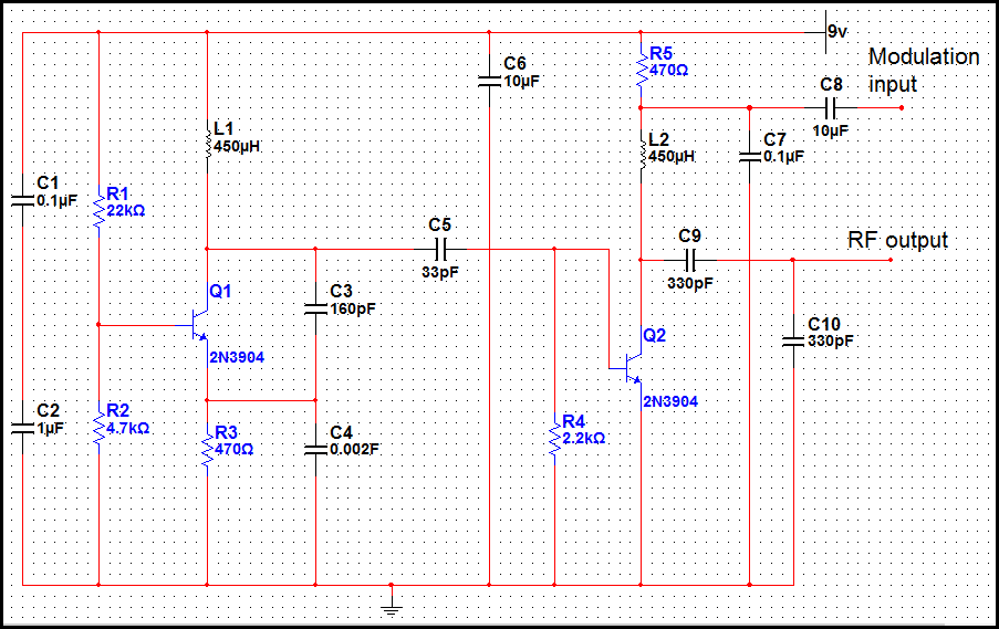
This transmitter is basic but allows the transmission of audio to an AM radio. It consists of an RF oscillator operating in the AM broadcast band, along with a modulator stage that mixes the incoming audio with the RF...
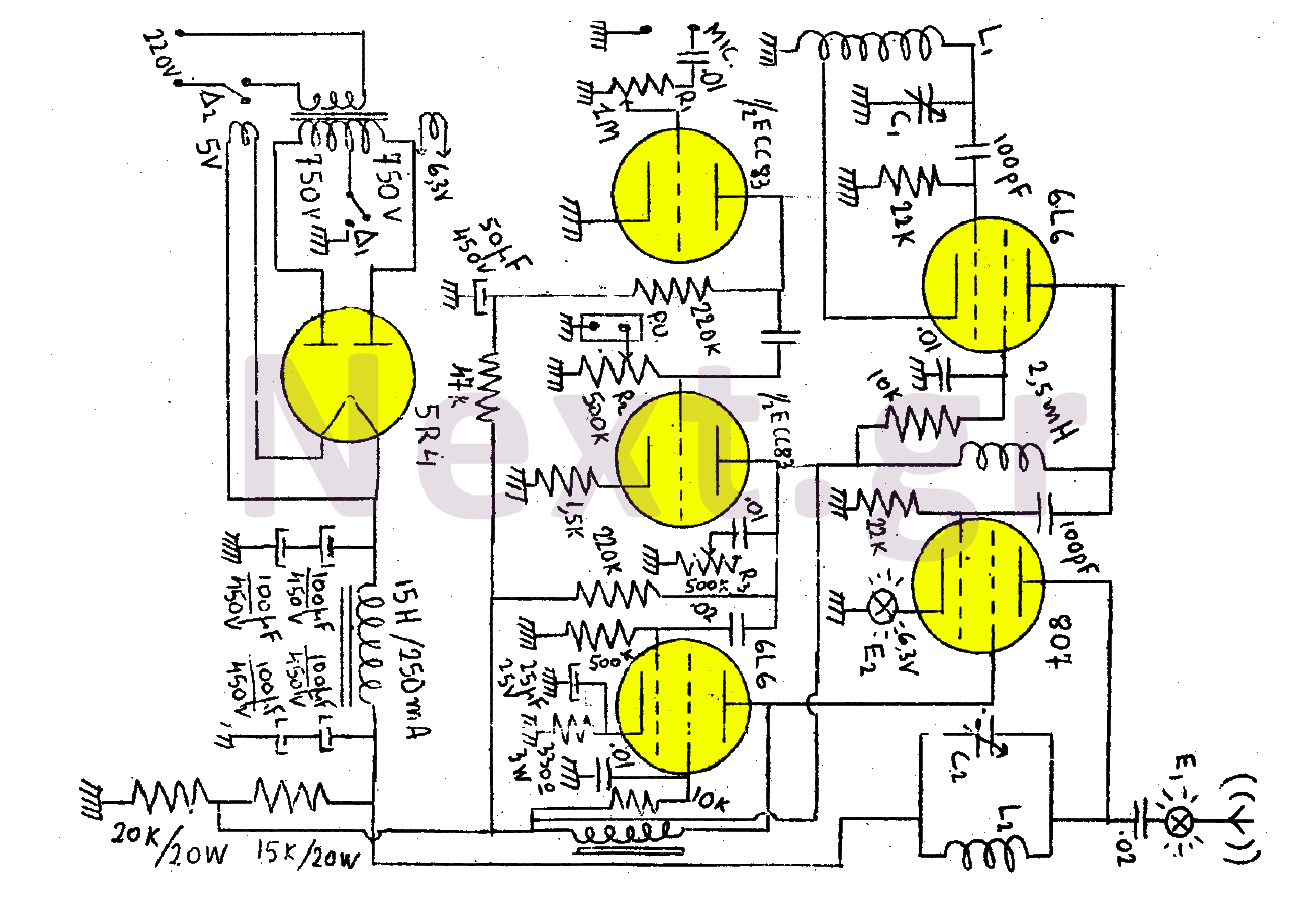
This transmitter consists of a total of five bulbs. The 6L6 tube functions as an oscillator, directing oscillations to the grid of the 807 tube, which serves as the final amplifier and the transmitter output lamp. The amplifier includes...

This is the BH1417 USB FM Transmitter, which features a built-in Phase-Locked Loop (PLL) circuit. It converts low-frequency audio signals into high-frequency signals, allowing any audio device equipped with an FM radio (such as stereo systems, car CD players,...