
88 108 MHz FM transmitter BF982 BF199 BFR90
The Colpitts oscillator is a type of electronic oscillator that utilizes a combination of capacitors and an inductor to generate a sine wave output. In the context of an 88-108 MHz FM transmitter, the oscillator is crucial for establishing the carrier frequency of the transmitted signal, which is typically within the FM broadcast band.
In this circuit, capacitors C3, C4, C5, and C6 are arranged in a manner that sets the oscillation frequency. The values of these capacitors, along with the inductance of L1, form a resonant LC circuit. The resonant frequency can be calculated using the formula:
\[ f = \frac{1}{2\pi\sqrt{LC}} \]
where \( f \) is the frequency, \( L \) is the inductance, and \( C \) is the total capacitance of the capacitors in the circuit. The combination of these components allows fine-tuning of the frequency, which is essential for compliance with FM broadcasting standards.
Diodes CD1 and CD2 may serve multiple functions in this circuit. They could be employed for frequency stabilization, providing feedback to the oscillator, or acting as part of a modulation scheme. Their placement and characteristics will significantly influence the performance and stability of the oscillator.
Additionally, the RF oscillator's output is typically fed into a power amplifier stage to boost the signal before transmission. This stage ensures that the signal can be radiated effectively to cover the desired area. Proper filtering and impedance matching are also necessary to ensure that the transmitter operates efficiently and minimizes interference with other frequencies.
Overall, the design of the Colpitts oscillator in this 88-108 MHz transmitter is fundamental to achieving stable and reliable frequency generation, which is vital for effective FM transmission.The most important part of this 88-108 transmitter is the Colpitts oscillator. C3,C4,C5,C6,CD1-CD2 ans L1 determine the transmission frequency. The RF Osci. 🔗 External reference
Related Circuits
This circuit operates at 73 MHz and is designed for controlling halogen lights through radio frequency remote control. The primary function is to toggle the power state of a halogen lamp. When the button on the remote control is...
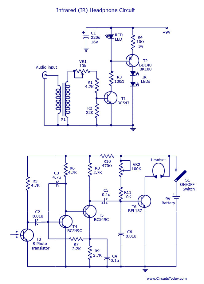
This document outlines a simple infrared (IR) headphone circuit designed for listening to television or radio without disturbing others. The IR headset is a preferable option for beginners compared to FM headsets due to its desirable sound quality that...

Transmitter RF Output LED Indicator Circuit Diagram. This RF output detector circuit, which includes a visual indicator, can be useful for an RF application. The transmitter RF output LED indicator circuit is designed to provide a visual representation of the...

In this circuit, U1 is a frequency converter that supplies the 455-kHz intermediate frequency (IF) stage U2 and detector U3. U4 serves as the audio output stage. R9 functions as a gain control, allowing for the adjustment of the...
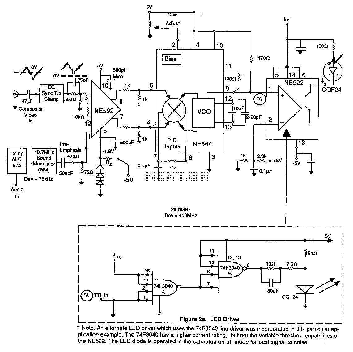
An alternate LED driver utilizing the 74F3040 line driver has been implemented in this application example. The 74F3040 offers a higher current rating but lacks the variable threshold capabilities found in the NE522. The LED diode operates in a...

This is the BH1417 USB FM Transmitter featuring a built-in PLL circuit. It converts low-frequency signals into high-frequency signals, allowing any audio device with FM radio capabilities (such as stereo systems, car CD players, MP3 players, and DVD players)...