
ultrasonic atomizer circuit

The ultrasonic atomizer circuit is designed to produce a fine mist of water by utilizing ultrasonic sound waves. This process involves the conversion of electrical energy into mechanical vibrations at ultrasonic frequencies, typically above 20 kHz. The primary component of this circuit is the ultrasonic transducer, which generates high-frequency sound waves that agitate the water, causing it to break into tiny droplets.
The circuit generally consists of a power supply, an oscillator, and the ultrasonic transducer. The power supply provides the necessary voltage and current to the circuit, while the oscillator generates a high-frequency signal that drives the transducer. The transducer, often made of piezoelectric materials, vibrates when energized, creating pressure waves in the water, leading to atomization.
To construct this circuit, the following components are typically required:
1. **Power Supply**: A suitable DC power source, usually between 12V to 24V, to power the circuit.
2. **Oscillator Circuit**: A simple oscillator can be built using a 555 timer IC configured in astable mode, generating a square wave output at the desired frequency.
3. **Ultrasonic Transducer**: A piezoelectric transducer rated for the desired operating frequency, which is responsible for converting the electrical signal into mechanical vibrations.
4. **Water Reservoir**: A small container to hold the water that will be atomized.
5. **Additional Components**: Resistors, capacitors, and possibly a transistor to amplify the output signal from the oscillator to drive the transducer effectively.
The assembly begins with connecting the power supply to the oscillator circuit, ensuring that the output frequency is tuned to match the resonant frequency of the ultrasonic transducer. The transducer is then submerged in the water reservoir, allowing it to generate sound waves that create the mist. Proper placement and orientation of the transducer are crucial for efficient atomization.
Safety considerations should be taken into account, including avoiding direct exposure to ultrasonic frequencies, which can be harmful at high intensities. Additionally, it is advisable to use distilled water to prevent mineral buildup on the transducer, which can affect performance.
Overall, the ultrasonic atomizer circuit is a practical and efficient solution for generating water mist for various applications, including humidification, aromatherapy, and decorative effects. Proper design and component selection are essential for optimal performance and reliability.Ultrasonic atomizer circuit : How to generate an atomized water mist using ultrasonic sound waves.. 🔗 External reference
Related Circuits
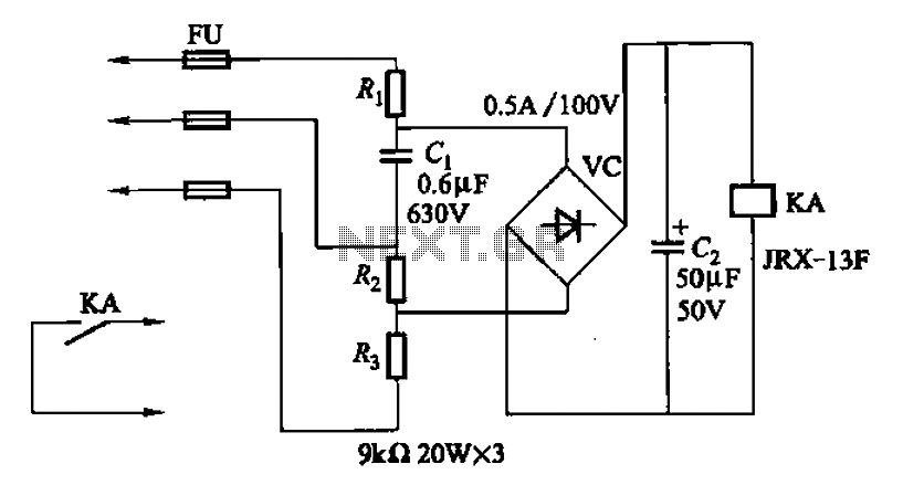
A capacitor C1 and resistors R1-R3 form a negative sequence voltage filtration device. The resistors and capacitors must meet the following requirements: R1, R2, R3 = 5.5/C1 (KN). The relationship between the resistance and capacitance values is arbitrary. Capacitor...
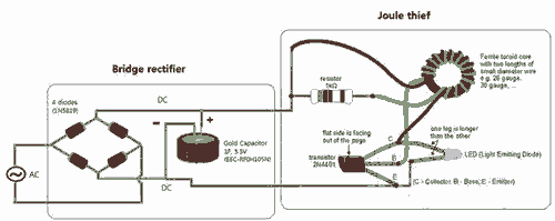
Breathe down and come out on the bright flashlight. In order to promote the voltage, pieces of a highly skilled Joule thief circuit have been used. The Joule thief circuit is a minimalist, low-power boost converter designed to extract energy...
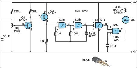
This design integrates power-on and low-battery indications, capable of operating with any battery voltage up to 15V. It features a very low current drain of 2mA or less and costs less than $3.50 with new components. When the battery...

Intercom walkie-talkies represent an advanced application of crystal oscillators for voice transmission. Utilizing a crystal-locked oscillator for voice transmission is complex due to the oscillator's fixed frequency, which is challenging to modulate. The primary method for achieving this involves...
This DC voltage doubler circuit generates a voltage that is double its supply voltage. It is beneficial when a higher voltage level is required from a single power source. The DC voltage doubler circuit typically employs a combination of capacitors...
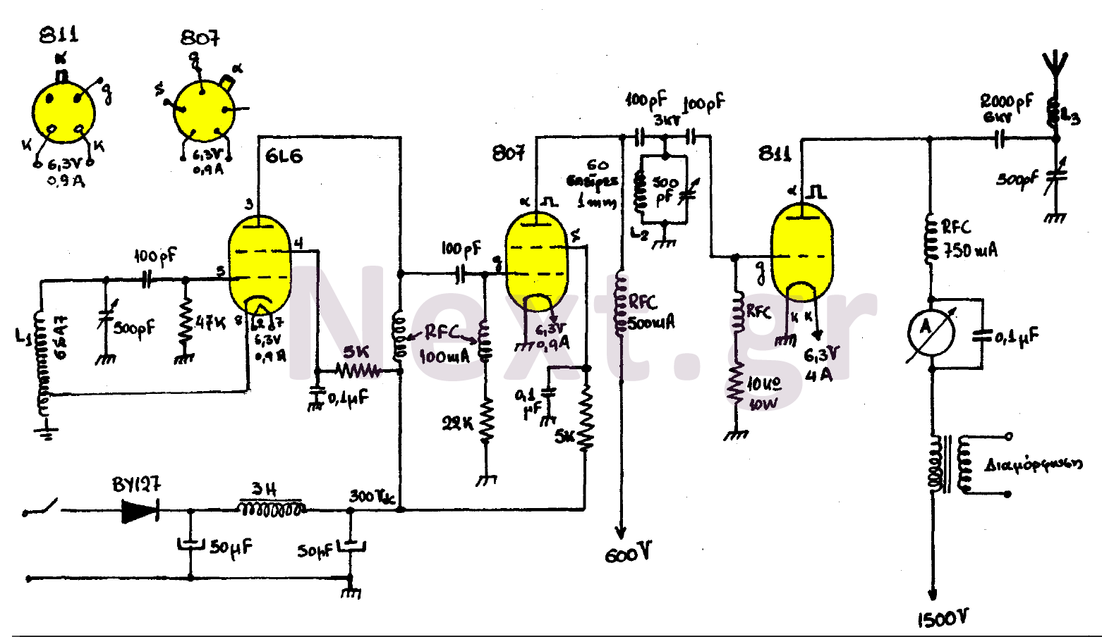
This transmitter consists of three stages: the oscillator stage utilizing a 6L6 tube, the amplifier isolator stage with an 807 tube, and the final stage of the transmitter featuring an 811 tube. The coil L1 is specified by the...