
DC Voltage Doubler Circuit with 555

The DC voltage doubler circuit typically employs a combination of capacitors and diodes to achieve its voltage multiplication effect. The circuit operates by charging capacitors to the supply voltage and then utilizing the diodes to transfer this charge in a manner that effectively doubles the output voltage.
In a basic configuration, the circuit consists of two diodes (D1 and D2) and two capacitors (C1 and C2). The input voltage is applied across C1, which charges to the supply voltage (Vs). During the first half of the AC cycle, D1 conducts, allowing C1 to charge. When the voltage reaches its peak, D1 becomes reverse-biased, and C2 begins to charge through D2. The voltage across C2 then rises to Vs + Vs, effectively doubling the output voltage.
The output can be taken from the junction between C2 and D2, providing a DC voltage that is twice the input voltage. This configuration is particularly useful in applications where higher voltage levels are necessary, such as in powering operational amplifiers, sensors, or other electronic components that require a voltage greater than what is available from the single supply.
It is important to consider the load that the circuit will drive, as the output voltage may sag under heavy load conditions. Additionally, the choice of diodes and capacitors will influence the efficiency and performance of the circuit. Schottky diodes are often preferred for their low forward voltage drop, which contributes to higher efficiency, while capacitors should be selected based on their voltage rating and capacitance value to ensure stable operation.
Overall, the DC voltage doubler circuit is a practical and effective solution for applications requiring higher voltage outputs from a lower voltage supply.This dc voltage doubler circuit produces a voltage that is twice its voltage supply. This is useful when a higher voltage level is needed out of a single l. 🔗 External reference
Related Circuits
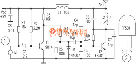
The circuit depicted utilizes a specialized launch tube T2 along with its associated components to create a high-frequency oscillator operating within the frequency range of 88 to 108 MHz. An electret microphone captures the audio signal, which is subsequently...
The TDA2030 is a monolithic integrated circuit in a Pentawat® package designed to function as a Class AB audio amplifier. It typically delivers up to 14 watts of output power (with a distortion rate of 0.5%) at 14V with...
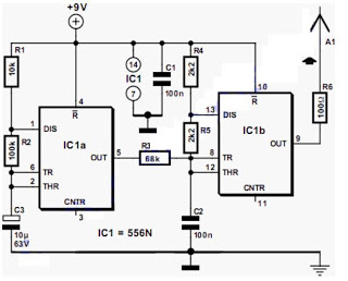
The output frequency alternates between approximately 2100 Hz and 2200 Hz. This unique test signal is easily distinguishable from other potential signals. Resistor R6 is connected to a wire, approximately ten centimeters long, which serves as the antenna. The...
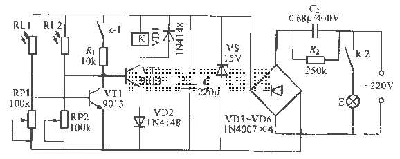
This is a remote-controlled light switch circuit that can be used for remote control toys, flashlight operation, or laser pointers. When the light from a torch illuminates the photosensitive resistor RL2, its resistance decreases, causing transistor VT2 to turn...
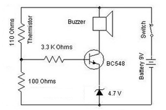
A heat sensor circuit can be utilized to control any device using a heat sensor. In this circuit, a thermistor and a resistor are connected in series, forming a potential divider circuit. The thermistor is of the Negative Temperature...
The primary issue with the design of a stereo amplifier that includes a total bass driver is that the signals from the left and right channels eventually become combined. This summation process minimizes the separation between channels, compromising the...