
ULTRASONIC PEST REPELLER

The circuit operates by employing the 555 timer in astable mode, allowing it to generate a continuous square wave output. The frequency of oscillation is primarily influenced by the external resistors R1 and R2, along with the capacitor C1, which together determine the timing intervals for the high and low states of the output signal. The values of these components can be adjusted to fine-tune the base frequency to the desired level.
In this configuration, pin 5 of the 555 timer is used for frequency modulation. The trapezoidal waveform applied to this pin alters the timing characteristics of the 555 timer, effectively varying the duty cycle of the output square wave. This modulation introduces a frequency sweep around the base frequency, enhancing the audio output characteristics when fed into the piezoelectric tweeter.
The bridge rectifier serves to convert any alternating current (AC) input into a direct current (DC) output, necessary for powering the circuit. The arrangement of C2, R3, and R4 across one leg of the bridge rectifier forms a voltage divider network, which shapes the modulating voltage. This voltage influences the modulation depth and frequency sweep, thus impacting the overall sound produced by the tweeter.
The 2-inch piezoelectric tweeter is selected for its ability to efficiently convert the electrical signal generated by the 555 timer into audible sound. The compact size of the tweeter allows for portability and versatility in applications, making it suitable for various electronic projects requiring sound output. The combination of frequency modulation and the characteristics of the tweeter contributes to a rich audio experience, making this circuit an effective solution for generating sound in electronic devices.This circuit is a 555 timer IC connected as a square-wave generator. Its base frequency is approximately 45 kHz, as determined by the values of R1, R2, and C1. The 45-kHz carrier is frequency modulated by a modified trapizoidal voltage waveform applied to pin 5 of the 555 timer. That modulating voltage is developed by a network consisting of C2, R 3, and R4 connected across one leg of the bridge rectifier. The sweep is approximately 20 kHz on each side of the base frequency. The speaker is a 2-inch piezoelectric tweeter. 🔗 External reference
Related Circuits
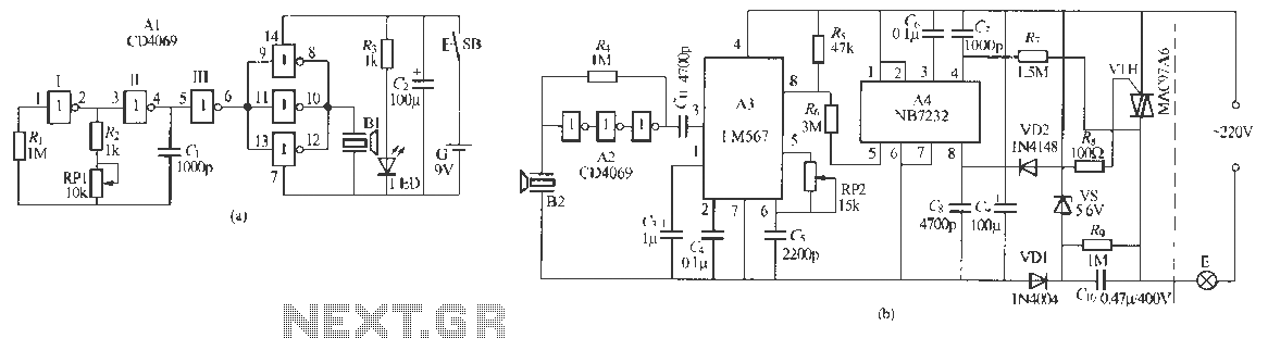
Remote control dimmer lights consist of two parts: an ultrasonic transmitter and an ultrasonic remote control dimmer receiver. The ultrasonic wave transmitter circuit is detailed in A 229 (a). It includes components such as R, R., RP1, and C,...
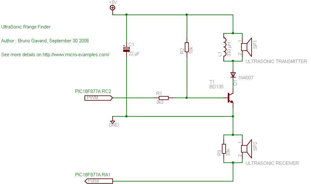
A cat deterrent system utilizing an Arduino, similar to existing models. Detection has been successfully implemented, and it has been determined that an ultrasonic transducer is required to generate the necessary deterrent sound. The proposed cat deterrent system employs an...
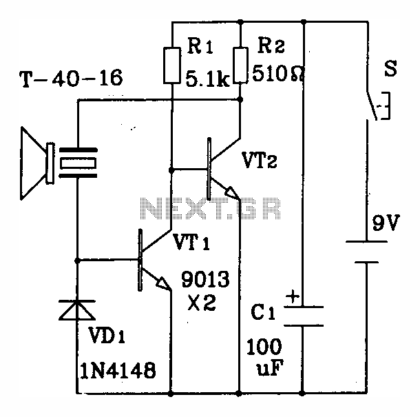
The discrete components ultrasonic transmitting circuit T/R-40-16 is capable of emitting a series of ultrasonic signals at a frequency of 40 kHz. This circuit operates at a voltage of 9V, with an operating current of 25 mA, and can...

The ultrasonic sensor controls and displays information through a buzzer or visual interface, alerting the driver to nearby obstacles using auditory signals or an intuitive display. This system alleviates issues related to stopping, reversing, and maneuvering around the vehicle,...

Enhancements include an analog front end, pin-to-pin compatibility for existing designs, an analog stabilized comparator, and simplified external circuit design. There is improved time and temperature measurement with reduced current consumption. The TDC-GP21 is ideally suited for designing compact...
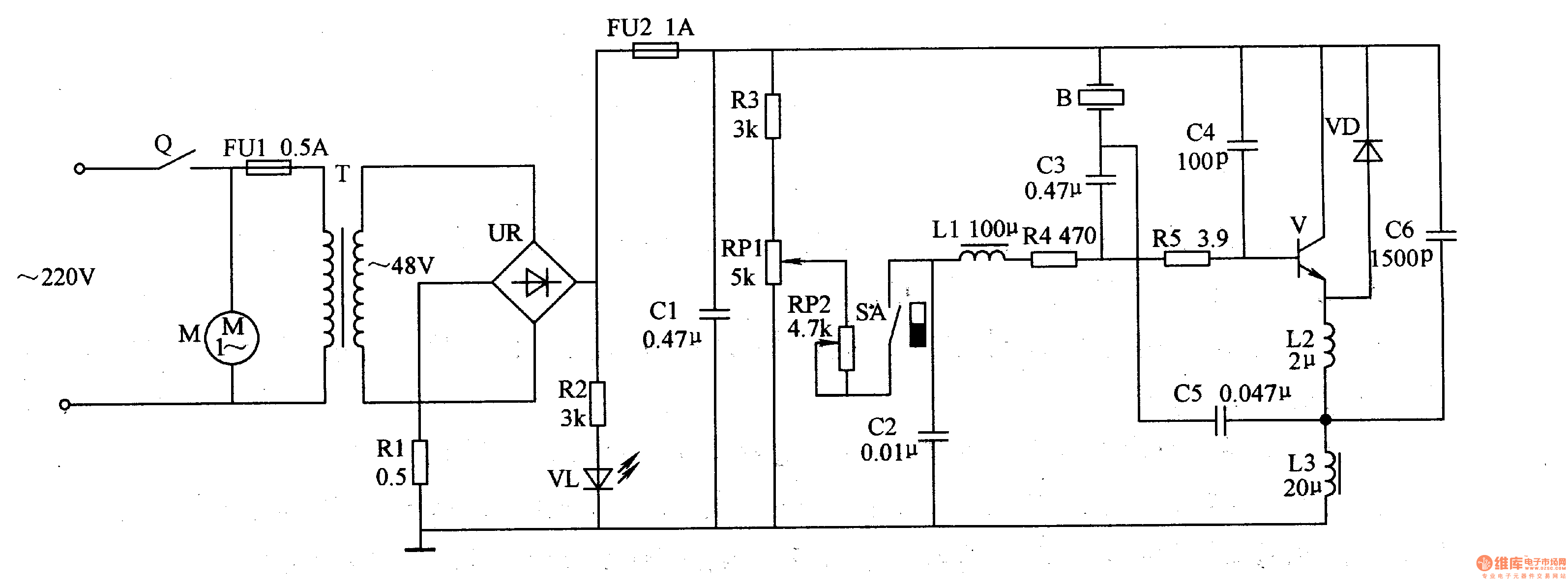
The medical ultrasonic atomizer circuit consists of a power supply circuit, an atomization amount liquid level detection control circuit, an ultrasonic oscillator, and a fan motor (M). The power supply circuit includes a timer (Q), fuses (FU1, FU2), a...