
UltraSonic Radars

Building electronic circuits on a printed circuit board (PCB) involves several fundamental principles. The PCB is composed of a thin insulating material coated with a thin layer of conductive copper, forming the necessary pathways between various circuit components. A well-designed PCB is advantageous as it accelerates construction and minimizes errors. Smart Kit boards are pre-drilled with component outlines and identifications printed on the component side to facilitate assembly. To prevent oxidation during storage and ensure pristine delivery, the copper is tinned during manufacturing and covered with a protective varnish that also eases soldering. Soldering components to the board is essential for circuit assembly, and the technique significantly impacts the project's success. The soldering iron must be lightweight, with a power rating not exceeding 25 watts. A fine tip should be maintained clean, using specially designed wet sponges to wipe off accumulated residues. If the tip cannot be cleaned, it should be replaced rather than filed or sanded. Choosing a high-quality solder containing the necessary flux in its core is crucial for achieving reliable joints.This is a very interesting project with many practical applications in security and alarm systems for homes, shops and cars. It consists of a set of ultrasonic receiver and transmitter which operate at the same frequency. When something moves in the area covered by the circuit the circuit ’s fine balance is disturbed and the alarm is triggered.
Th e circuit is very sensitive and can be adjusted to reset itself automatically or to stay triggered till it is reset manually after an alarm. As it has already been stated the circuit consists of an ultrasonic transmitter and a receiver both of which work at the same frequency.
They use ultrasonic piezoelectric transducers as output and input devices respectively and their frequency of operation is determined by the particular devices in use. The transmitter is built around two NAND gates of the four found in IC3 which are used here wired as inverters and in the particular circuit they form a multivibrator the output of which drives the transducer.
The trimmer P2 adjusts the output frequency of the transmitter and for greater efficiency it should be made the same as the frequency of resonance of the transducers in use. The receiver similarly uses a transducer to receive the signals that are reflected back to it the output of which is amplified by the transistor TR3, and IC1 which is a 741 op-amp.
The output of IC1 is taken to the non inverting input of IC2 the amplification factor of which is adjusted by means of P1. The circuit is adjusted in such a way as to stay in balance as long the same as the output frequency of the transmitter.
If there is some movement in the area covered by the ultrasonic emission the signal that is reflected back to the receiver becomes distorted and the circuit is thrown out of balance. The output of IC2 changes abruptly and the Schmitt trigger circuit which is built around the remaining two gates in IC3 is triggered.
This drives the output transistors TR1, 2 which in turn give a signal to the alarm system or if there is a relay connected to the circuit, in series with the collector of TR1, it becomes activated. The circuit works from 9-12 VDC and can be used with batteries or a power supply. First of all let us consider a few basics in building electronic circuits on a printed circuit board.
The board is made of a thin insulating material clad with a thin layer of conductive copper that is shaped in such a way as to form the necessary conductors between the various components of the circuit. The use of a properly designed printed circuit board is very desirable as it speeds construction up considerably and reduces the possibility of making errors.
Smart Kit boards also come pre-drilled and with the outline of the components and their identification printed on the component side to make construction easier. To protect the board during storage from oxidation and assure it gets to you in perfect condition the copper is tinned during manufacturing and covered with a special varnish that protects it from getting oxidised and also makes soldering easier.
Soldering the components to the board is the only way to build your circuit and from the way you do it depends greatly your success or failure. This work is not very difficult and if you stick to a few rules you should have no problems. The soldering iron that you use must be light and its power should not exceed the 25 Watts. The tip should be fine and must be kept clean at all times. For this purpose come very handy specially made sponges that are kept wet and from time to time you can wipe the hot tip on them to remove all the residues that tend to accumulate on it.
DO NOT file or sandpaper a dirty or worn out tip. If the tip cannot be cleaned, replace it. There are many different types of solder in the market and you should choose a good quality one that contains the necessary flux in its core, to assure a perfect joint every time. DO NOT use so 🔗 External reference
Related Circuits
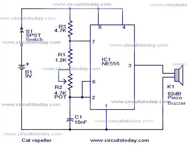
This cat and dog repeller circuit is designed to deter animals from specific areas. The circuit utilizes ultrasonic sound, which is known to provoke a strong response in many animals, particularly cats. The design features an astable multivibrator configuration...
The alarm detector circuit operates differently from the Ultrasonic Alarm (1). In Ultrasonic Alarm (1), an alarm output is triggered by the detection of a reflected wave from an object during the setup time. Conversely, in this circuit, an...

This project has numerous practical applications in security and alarm systems for homes, shops, and vehicles. It consists of a set of ultrasonic receivers and transmitters operating at the same frequency. When movement occurs in the area monitored by...

The first sensor that a robot is typically equipped with is an obstacle detector. It can take three different forms, depending on the type of obstacle to be detected. Obstacle detectors are essential components in robotic systems, designed to enhance...
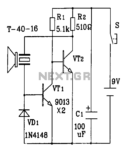
The discrete components ultrasonic transmitter circuit T/R-40-16 can emit a series of ultrasonic signals at a frequency of 40 kHz. This circuit operates at a voltage of 9V and has a current consumption of 25mA, with a control distance...
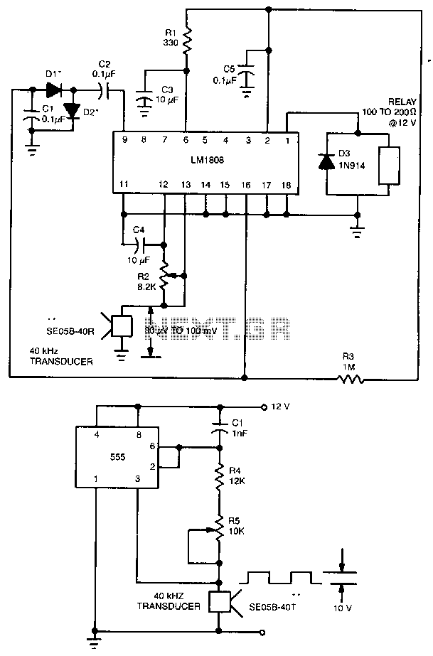
This ultrasonic transmit/receive circuit operates at 40 kHz. Control resistor R5 adjusts the frequency for optimal performance with the transducers used. The ultrasonic transmit/receive circuit designed to operate at a frequency of 40 kHz is essential for applications in distance...