
Cat Repeller CircuitRepellentCircuit555 Ultrasonic Circuit

The circuit functions primarily as an ultrasonic deterrent, leveraging the sensitivity of cats and dogs to high-frequency sounds that are inaudible to humans. The NE555 timer IC is configured in an astable mode, which enables it to oscillate continuously, generating a square wave output. This output drives the piezo buzzer, producing the desired ultrasonic frequencies.
The frequency produced can be adjusted by varying the resistance of the potentiometer (R2), which alters the timing components in the NE555 circuit. The frequency range of 15-20 kHz is particularly effective for repelling cats, as it falls within the range of sounds that they can hear but humans cannot.
While the circuit is designed to be straightforward and effective, it is essential to recognize that individual animals may respond differently. Some may become desensitized to the sound over time, necessitating adjustments to the frequency to maintain its deterrent effect.
Overall, this circuit represents a practical solution for individuals seeking a humane method to keep pets away from designated areas without resorting to physical barriers or harmful substances. The simplicity of the design, combined with the effectiveness of ultrasonic sound, makes it an appealing option for pet owners.With this cool cat/dog repeller circuit you could chase the cats off from any where you want. In fact, I designed this circuit to chase my cat from my computer table. Most of the animals like cats respond violently to ultrasonic sound and in fact it`s the best way to chase them off. This principle is employed in this circuit. The circuit here is n othing but an astable multivibrator wired around NE555 (IC1). The cat repellent circuit produces an ultrasonic sound in the range 15-20Khz. The NE 555 is enough to drive a small piezo buzzer and no amplification stages are needed. The POT R2 can be used to adjust the frequency of sound. I do not guarantee the full effectiveness of the circuit. You have try a lot of frequency settings to make your cat feel discomfort at last. More over the cat may get accustomed to the sound after some time. For me the circuit was only a partial success and now my cat feels nothing even if the speaker is placed in it`s ear. You try your luck. Best of luck. 🔗 External reference
Related Circuits
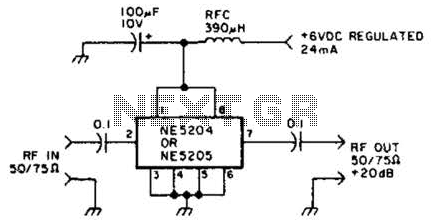
The Signetics NE5204 or NE5205 can be utilized in this audio frequency to 350-MHz (-30 dB) preamplifier. For a requirement of 600 MHz at 3 dB, the NE5205 should be employed. The noise figure is 4.8 dB at 75...
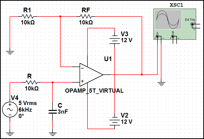
High-order filters are typically designed with two or more cascaded sections. An order 4 filter requires only one operational amplifier integrated circuit (OA IC), allowing for lower distortion. High-order filters are essential in various applications, including audio processing, signal conditioning,...

This circuit is used to select modes of operation. The accelerometer is utilized to generally move the snake arm, while the Hall effect sensors are designed to enable various functions. The circuit described incorporates an accelerometer and Hall effect sensors...
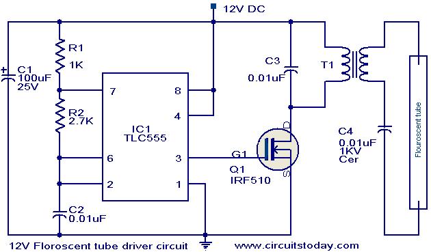
This circuit provides a simple and effective method for driving fluorescent lamps using a 12 V power supply. The circuit consists of an oscillator, a MOSFET switch, and a step-up transformer to power the fluorescent lamp. The TLC 555...

The simplest example of a Switch Mode Power Supply (SMPS) utilizes three transistors (C3807, A1015, and power transistors). A common issue that arises is related to the feedback circuit, which can lead to an output voltage (B+) that exceeds...
This circuit counts the flashes of turn signals. After approximately 70 flashes, a chime sounds to remind the driver to deactivate the turn signal. The period can be altered by using different taps on U2 if desired. BZ1 serves...