
ultrasonic switch sensor
The circuit design employs a 555 timer in astable mode to generate a continuous ultrasonic signal. The frequency is adjustable within the range of 40 kHz to 50 kHz, depending on the resistor and capacitor values used in the timer configuration. The ultrasonic transducer converts the electrical signal from the 555 timer into ultrasonic waves, which are then transmitted in a directional manner.
On the receiving end, the ultrasonic receiver transducer captures the emitted ultrasonic waves and converts them back into electrical signals. These signals are then processed through a two-stage amplifier comprising two transistors (T3 and T4), which amplify the weak signals to a level suitable for further processing. Following amplification, a rectifier circuit converts the AC signals into DC, which is then filtered to smooth out any fluctuations.
The operational amplifier (IC2) plays a critical role in determining whether the relay should be actuated. The variable resistor (VR2) allows for fine-tuning of the sensitivity of the receiver circuit, ensuring that it only activates when a sufficient ultrasonic signal is detected. The relay driver stage ensures that the relay can be controlled effectively, allowing for the switching of larger loads.
For applications requiring latch functionality, a double-pole double-throw (DPDT) relay can be incorporated, enabling the circuit to maintain the relay in an active state until manually reset. Additionally, a flip-flop can be integrated into the circuit to provide a more sophisticated control mechanism, ensuring that the relay remains energized for a predetermined duration.
The directional nature of ultrasonic sound necessitates careful alignment between the transmitter and receiver to avoid false triggering, which can occur due to interference from natural ultrasonic sources. Adjustments to the circuit may be necessary to mitigate these effects, especially in environments with significant ultrasonic noise.This circuit functions with inaudible (ultrasonic) sound. Sound of frequency up to 20 kHz is audible to human beings. The sound of frequency above 20 kHz is called ultrasonic sound. The circuit described generates (transmits) ultrasonic sound of frequency between 40 and 50 kHz. As w ith any other remote control system this cirucit too comprises a mini transmitter and a receiver circuit. Transmitter generates ultrasonic sound and the receiver senses ultrasonic sound from the transmitter and switches on a relay.
The ultrasonic transmitter uses a 555 based astable multivibrator. It oscillates at a frequency of 40-50 kHz. An ultrasonic transmitter transducer is used here to transmit ultrasonic sound very effectively. The transmitter is powered from a 9-volt PP3 single cell. The ultrasonic receiver circuit uses an ultrasonic receiver transducer to sense ultrasonic signals. It also uses a two-stage amplifier, a rectifier stage, and an operational amplifier in inverting mode. Output of op-amp is connected to a relay through a complimentary relay driver stage. A 9-volt battery eliminator can be used for receiver circuit, if required. When switch S1 of transmitter is pressed, it generates ultrasonic sound. The sound is received by ultrasonic receiver transducer. It converts it to electrical variations of the same frequency. These signals are amplified by transistors T3 and T4. The amplified signals are then rectified and filtered. The filtered DC voltage is given to inverting pin of op-amp IC2. The non- inverting pin of IC2 is connected to a variable DC voltage via preset VR2 which determines the threshold value of ultrasonic signal received by receiver for operation of relay RL1.
The inverted output of IC2 is used to bias transistor T5. When transistor T5 conducts, it supplies base bias to transistor T6. When transistor T6 conducts, it actuates the relay. The relay can be used to control any electrical or electronic equipment. Important hints: 2. Ultrasonic sounds are highly directional. So when you are operating the switch the ultrasonic transmitter transducer of transmitter should be placed towards ultrasonic receiver transducer of receiver circuit for proper functioning. 4. For latch facility use a DPDT relay if you want to switch on and switch off the load. A flip-flop can be inserted between IC2 and relay. If you want only an ½ON-time delay ½ use a 555 only at output of IC2. The relay will be energised for the required period determined by the timing components of 555 monostable multivibrator.
5. Ultrasonic waves are emitted by many natural sources. Therefore, sometimes, the circuit might get falsely triggered, espically when a flip-flop is used with the circuit, and there is no remedy for that 🔗 External reference
Related Circuits
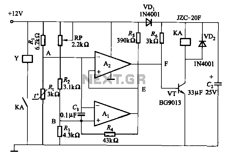
Electronic temperature control circuit for imported car air conditioners. It utilizes operational amplifiers A1 and A2, specifically the LM393 model. An adjustment potentiometer (RP) is included, allowing modification of the temperature range. The adjustment range includes a power temperature...
This light sensor switch circuit enables the automatic activation of a lamp when ambient light levels are low, such as during nighttime. The circuit keeps the lamp illuminated for a predetermined duration. When transistors T4 and T5 are activated,...
The circuit is designed to create a universal infrared switch with a single channel and ON/OFF functionality, operating in the frequency range of 36 kHz to 38 kHz, suitable for remote control applications. Infrared is a segment of the...

This circuit serves as an alarm system suitable for both home security and personal belongings such as handbags. When installed in a home, it can be positioned on doors or windows, and when used for bags, it provides a...
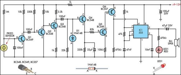
This circuit utilizes a thin piezoelectric sensor to detect vibrations caused by impacts on a surface, such as a door or table. Essentially, it amplifies and... The circuit design incorporates a piezoelectric sensor, which is sensitive to mechanical stress and...
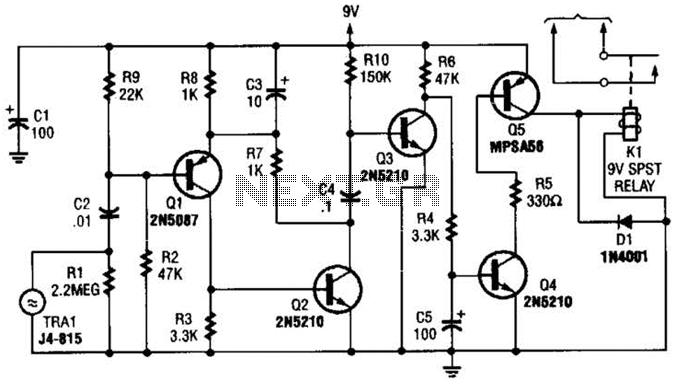
A GC Electronics P/N J4-815 transducer is utilized to receive 40-kHz acoustic remote-control signals. The receiver activates a relay to control another circuit. The GC Electronics P/N J4-815 transducer is designed specifically for the reception of 40-kHz acoustic signals, which...